Wind turbine with element for sealing two parts that can be rotated in relation to one another

A technology for seals and components, which is applied in the field of components used to seal two components that can be twisted relative to each other, can solve the problems of roughening, destruction, and surface damage of the seals, and achieve the effect of uniform pressing force

Inactive Publication Date: 2008-09-03
IMO HOLDING GMBH
View PDF0 Cites 15 Cited by
  • Summary
  • Abstract
  • Description
  • Claims
  • Application Information

AI Technical Summary

Problems solved by technology

But as long as it is corroded, the seal will be damaged by the surface roughened thereby and eventually destroyed

Method used


Image

  • Wind turbine with element for sealing two parts that can be rotated in relation to one another
  • Wind turbine with element for sealing two parts that can be rotated in relation to one another
  • Wind turbine with element for sealing two parts that can be rotated in relation to one another

Examples


Embodiment Construction

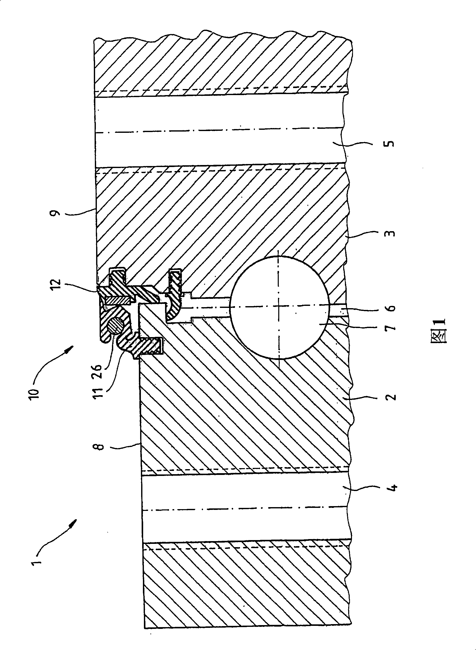
[0044] The ball bearing 1 of FIG. 1 consists of two concentric rings which can be rotated relative to each other. The outer ring 2 can be seen on the left in FIG. 1 and the inner ring 3 can be seen on the right. The two rings 2, 3 are passed through by fixed holes 4, 5 parallel to the axis of rotation. In the region of the gap 6 between the two rings 2 , 3 there is a raceway of at least one row of spherical rolling bodies 7 which allow the relative torsion of the two rings 2 , 3 as a single degree of freedom of movement. On the ball bearing 1, the upper end faces 8, 9 in FIG. 1 are exposed to the open air. For this reason, the gap 6 between the two end faces 8 , 9 is sealed with the seal 10 according to the invention.

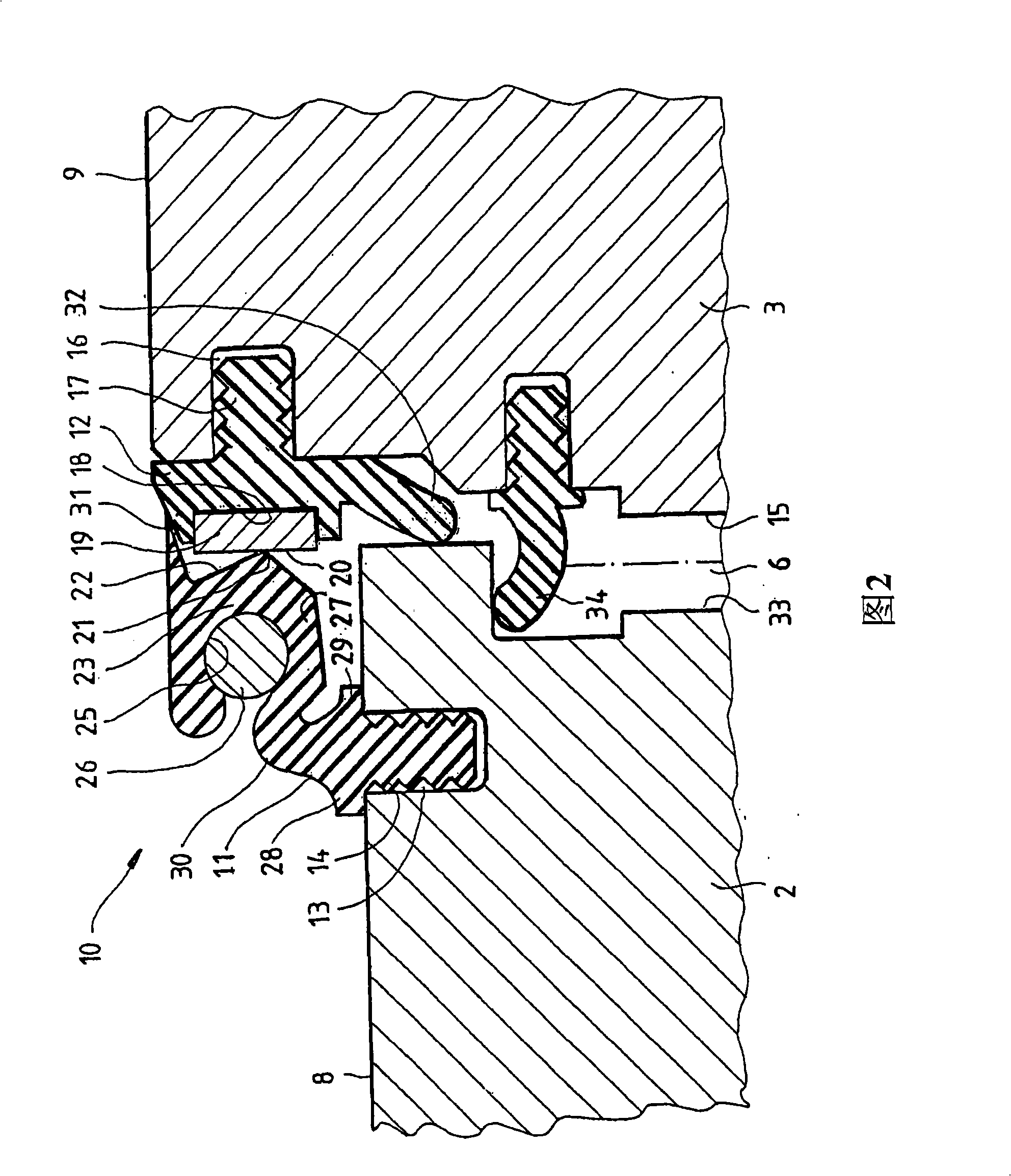
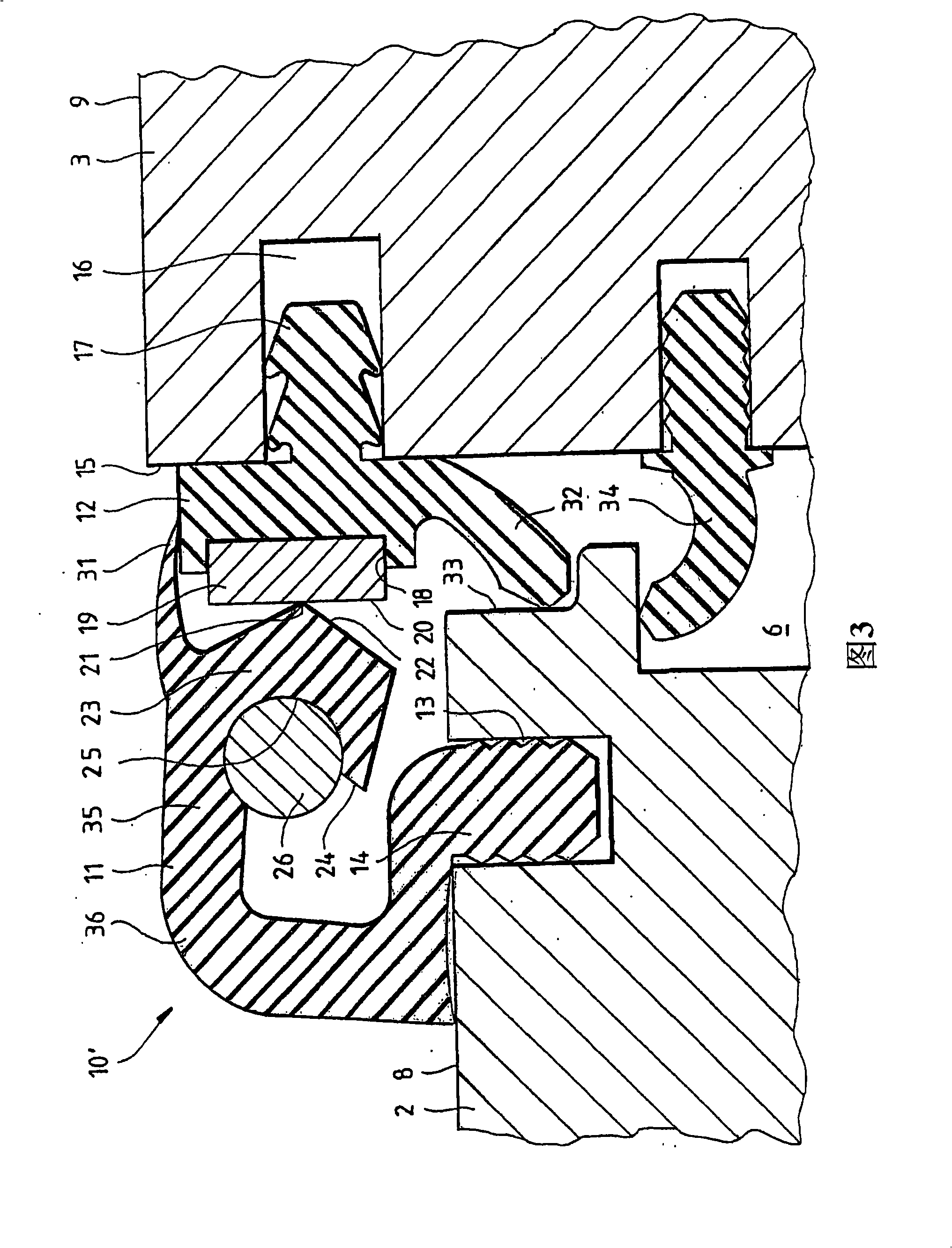
[0045] As shown in FIG. 2 , the sealing member 10 consists of a first sealing ring 11 and a second sealing ring 12 , each of which is composed of a vulcanized material, such as vulcanized natural or synthetic rubber. The first sealing ring 11 is fixed on the...


PUM


Abstract

The invention relates to an element (10) for sealing two parts (2, 3) that can be rotated in relation to one another. Said element comprises at least one first sealing ring (11) consisting of a permanently elastic material, which is fixed to one of the two rotatable parts and comprises at least one sealing lip (21) and at least one second sealing ring (12), which is fixed to the other rotatable part and comprises a strip (19) consisting of another material that runs along its periphery. At least one sealing lip of the first sealing ring lies against said strip.

Description

technical field [0001] The invention relates to an element for sealing two parts that can be rotated relative to each other, having at least one first sealing ring made of a durable elastic material, fixed to one of the two parts that can be rotated relative to one another and having At least one sealing lip. Background technique [0002] Common seals on the market are mostly composed of a ring made of elastic material, which is fixed on one of two parts that can be twisted relative to each other and has a sealing lip, which is pressed sealingly against two parts that can be rotated relative to each other. Twist the other part of the piece. In order that the sealing lip does not fail prematurely, the contact surface should be as flat as possible. Usually a turned and / or polished surface area of ​​the relevant rotating part is used for this purpose, which is also preserved if necessary by a grease film. But this setup has flaws: [0003] On large bearings, especially in t...

Claims


Application Information

Patent Timeline
Patent Type & Authority Applications(China)
IPC IPC(8): F16J15/00F16C33/78F16J15/32F16C19/16F16J15/54
CPCF16C19/163F16C33/7886F16C33/7896F16C2300/14F16J15/002F16J15/3232F16J15/3264F16J15/54F16C33/76F16C2360/31
Inventor 埃里希·鲁斯弗兰克·胡贝图斯赫尔曼·维拉切克
Owner IMO HOLDING GMBH
Why Eureka
Try Eureka