A catheter steering system

A catheter and guiding mechanism technology, applied in catheters, medical science, sensors, etc., can solve problems such as precious space

Inactive Publication Date: 2008-09-10
CATHRX LTD
View PDF0 Cites 14 Cited by
  • Summary
  • Abstract
  • Description
  • Claims
  • Application Information

AI Technical Summary

Problems solved by technology

Therefore, space in the

Method used


Image

  • A catheter steering system
  • A catheter steering system

Examples


Embodiment Construction

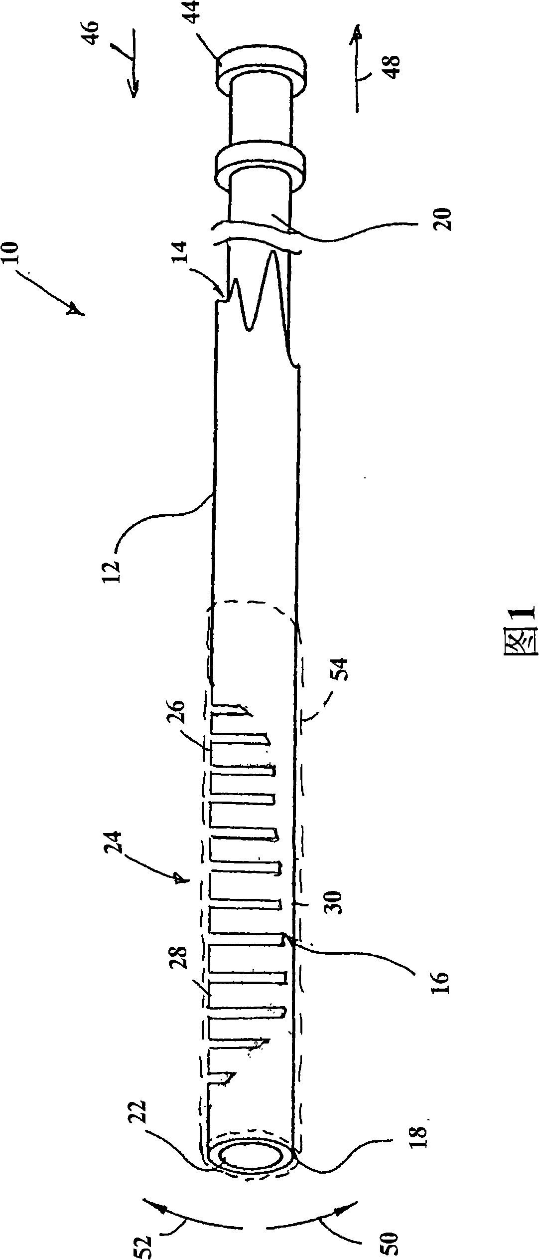
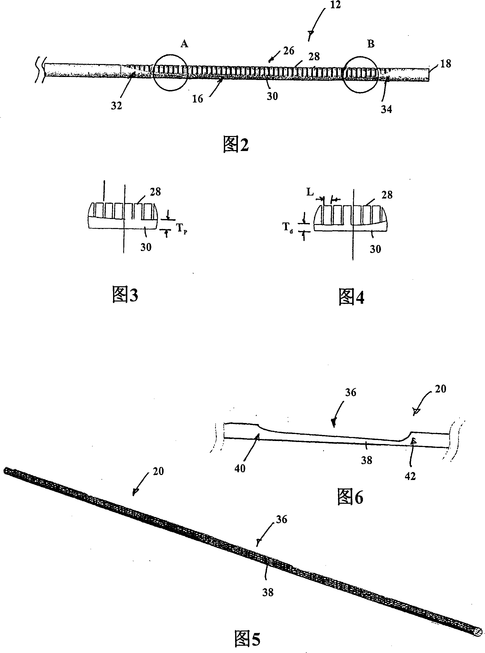
[0032] In the drawings, reference numeral 10 generally denotes a catheter guiding mechanism according to an embodiment of the present invention. The catheter guide mechanism includes a tubular member 12 defining a channel 14 . The tubular member 12 has a longitudinally extending notched portion 16 proximate a distal end 18 thereof. The notched portion 16 defines a bend enhancement zone within the tubular member 12 . An elongated actuator 20 is housed within the channel 14 of the tubular member 12 . The distal end 22 of the actuator 20 is fixedly secured to the distal end 18 of the tubular member 12 .

[0033] The tubular member 12 defines a restriction 24 . The restraint device 24 includes a cage formation 26 arranged at the bending reinforcement region 16 of the tubular member 12 .

[0034] In this embodiment, the actuator 20 is a solid actuator, but a person skilled in the art will readily appreciate that the actuator could also be tubular.

[0035] Both the tubular par...


PUM


Abstract

A catheter steering mechanism 10 includes a tubular member 12 defining a passage 14 . The tubular member 12 has a longitudinally extending, cutaway portion 16 defining a bend-enhancing region formed at a predetermined location along a length of the tubular member 12 . An actuator 20 is received in the passage 14 of the tubular member 12 , a distal part 22 of the actuator 20 being fast with a distal part of the tubular member 12 . A restraining arrangement 24 is defined by the tubular member 12 , the restraining arrangement 24 comprising a structure 26 arranged at the bend-enhancing region to retain the actuator 20 substantially within the confines of the tubular member 12 during bending.

Description

[0001] Cross References to Related Applications [0002] This application claims priority to US Provisional Patent Application No. 60 / 861,642, filed November 28, 2006, the contents of which are hereby incorporated by reference. technical field [0003] The present invention relates generally to a catheter guiding system, and more particularly to a catheter guiding mechanism and a steerable catheter including the guiding mechanism. Background technique [0004] Electrophysiology catheters are medical devices used to measure electrical signals within the heart and are commonly used in diagnosing various cardiac arrhythmias. Certain types of these catheters are also used to treat cardiac arrhythmias through ablation techniques. [0005] Typically, the catheter is inserted through the patient's femoral vein in order to be able to reach the area of ​​the heart to be treated. The tip of the catheter is guided through the patient's vasculature to the desired location. Similarly,...

Claims


Application Information

Patent Timeline
IPC IPC(8): A61B5/042A61M25/01
CPCA61M25/0105A61M25/0133A61M25/0138
Inventor 马修·J·帕尔莱特
Owner CATHRX LTD
Why Eureka
Try Eureka