

Automobile front collision energy-absorbing device and assembling method thereof
An energy-absorbing device and front-collision technology, which is applied to vehicle components, transportation and packaging, and substructure, can solve problems such as intrusion, bending and deformation of the front cabin longitudinal beam floor, and affecting occupant safety, so as to alleviate the degree of deformation and improve collision Safety performance, solve the effect of energy absorption
- Summary
- Abstract
- Description
- Claims
- Application Information
AI Technical Summary
Problems solved by technology
Method used
Image

Examples
Embodiment 1
[0037] This embodiment provides a specific form of the longitudinal beam connecting plate structure.
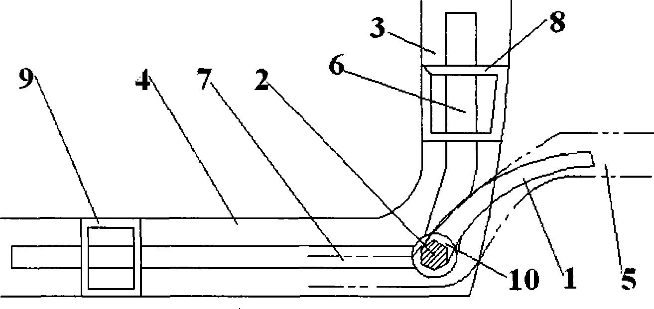
[0038] That is: the height of the front cabin longitudinal beam 5 extending in the direction of the twisted beam 2 is higher than that of the twisted beam 2, and the described longitudinal beam connecting plate 1 is a curved member connecting the two, and the bending direction is from the front cabin longitudinal beam. 5 bends to the rear and the bottom of the vehicle body until the end connected with the torsion beam 2.
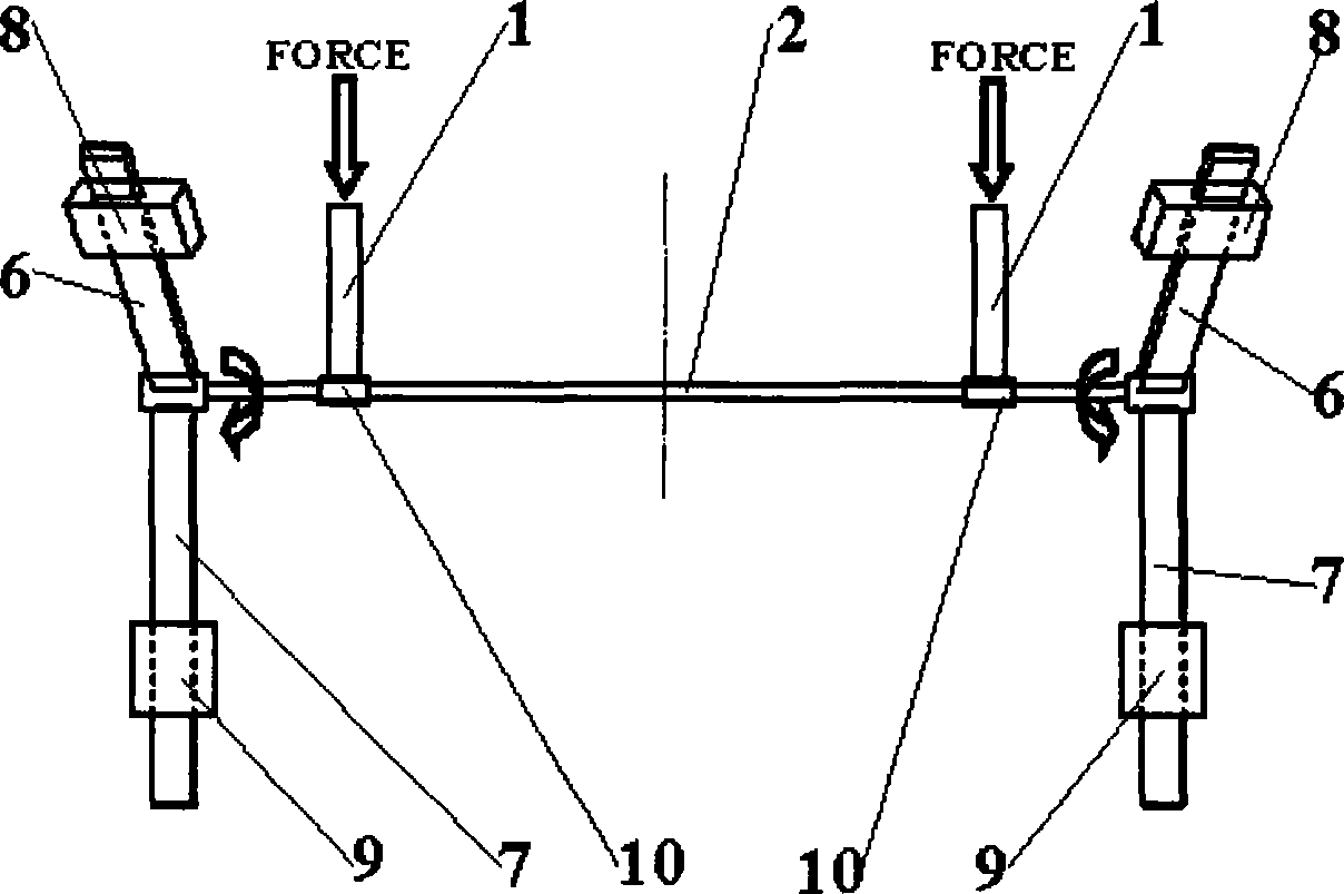
[0039]The setting of the above-mentioned structure makes the longitudinal beam connecting plate 1 adapt to the structural form of the front cabin longitudinal beam 5, and ensures that it will not directly act on the torsion beam 2 in the form of force after it is stressed, but in the form of moment. The form loads the torsion beam 2, causing it to undergo a certain torsional deformation, so that the torsion beam 2 can transmit energy on the one hand, and st...
Embodiment 2
[0041] This embodiment is a specific structural form in which the longitudinal beam connecting plate 1 is connected to the twisted beam 2 .
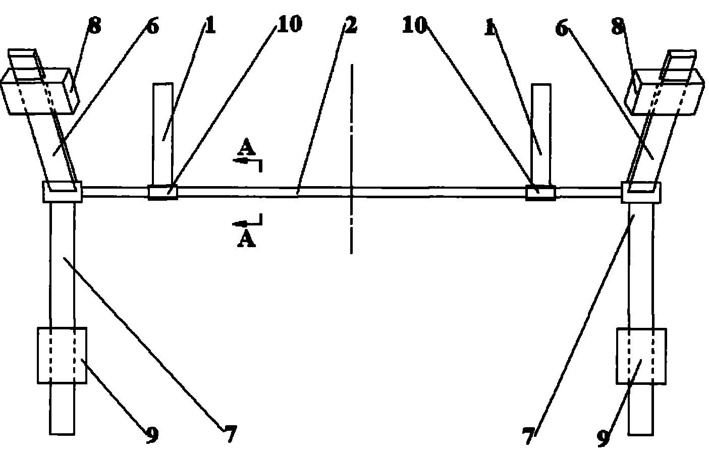
[0042] The longitudinal beam connecting plate connection sleeve 10 is provided, the longitudinal beam connecting plate 1 connects the sleeve 10 and the twisted beam 2 through the longitudinal beam connecting plate, and the cross section of the twisted beam 2 is in the shape of a spline, or a tooth shape, or a polygon, Or ellipse, the cross-section of the hole where the connecting sleeve 10 of the longitudinal beam connecting plate is sleeved on the twisted beam 2 is a shape matched with the shape of the cross-section of the twisted beam 2 .
[0043] The positions near both ends of the torsion beam 2 are connected to the two longitudinal beam connecting plates 1 through two longitudinal beam connecting plate connecting sleeves 10; On the reinforced inner plate of the neck (i.e. adapting to the bending position of the vehicle body), the en...
Embodiment 3
[0045] This embodiment provides a specific structural form in which the door hinge post mounting bracket 6 and the door sill mounting bracket 7 are connected on the door hinge post 3 and the door sill 4 .
[0046] A door hinge column fixing seat 8 and a threshold fixing seat 9 are provided, and the door hinge column mounting bracket 6 is tightly connected with the door hinge column 3 through the door hinge column fixing seat 8; It is firmly connected with the door sill 4.
[0047] The above structure ensures that the torsion beam 2 can be tightly connected to the door hinge column 3 and the threshold 4 on both sides of the vehicle body through the door hinge column mounting bracket 6 and the door sill mounting bracket 7, so that when a collision occurs, the energy is evenly distributed to various parts of the vehicle body. Reduce collision losses.
PUM
 Abstract
Description
Claims
Application Information