
Steel bar positioning structure for building construction

A positioning structure and building construction technology, applied in the direction of building structure, construction, building materials processing, etc., can solve the problems of easy displacement and deflection of steel bars, inconvenient disassembly, inconvenient handling and transportation, etc., to achieve improvement Overall stability, ease of handling, and strength-enhancing effects

Inactive Publication Date: 2020-12-08
浙江富成建设集团有限公司
View PDF7 Cites 2 Cited by
  • Summary
  • Abstract
  • Description
  • Claims
  • Application Information

AI Technical Summary

Problems solved by technology

However, due to the influence of steel bar installation and concrete pouring, the steel bars are prone to shift and deflection, so it is necessary to position the steel bars to prevent them from shifting
Existing reinforcing bar positioning structure (such as the utility model patent whose patent publication number is CN204357007U), its structure is simple, and it is inconvenient to disassemble during positioning and correction, and it is inconvenient to carry and transport

Method used


Image

  • Steel bar positioning structure for building construction
  • Steel bar positioning structure for building construction
  • Steel bar positioning structure for building construction

Examples


Embodiment 1

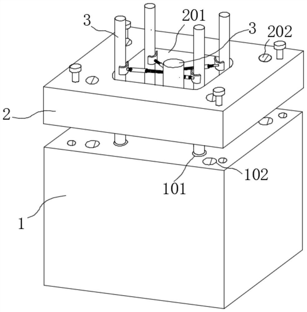
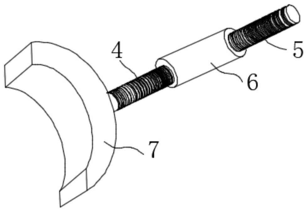
[0026] Example 1: See Figure 1-2 , the present invention provides a technical solution: a steel bar positioning structure for building construction, including a positioning seat 1, a positioning template 2 and a first positioning mechanism, the positioning seat 1 is in the shape of a rectangular column and its end is provided with a through-type multiple A first through hole 101 and a second through hole 102, the four corners of the end of the positioning seat 1 are provided with first screw holes; a plurality of the first through holes 101 and the second through holes 102 are distributed in the positioning seat in a rectangular array 1 end face, the first through hole 101 is located inside the second through hole 102, and the inside of the first through hole 101 and the second through hole 102 are both pierced with steel bars; the positioning template 2 is placed directly above the positioning seat 1, and the positioning template 2 The four corners are connected and matched ...

Embodiment 2

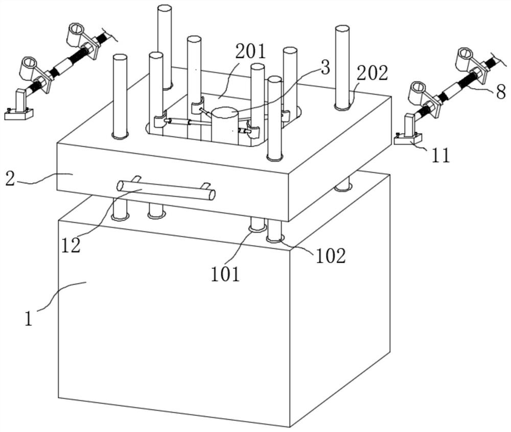
[0030] Example 2: see Figure 3-5, the present invention provides a technical solution: a steel bar positioning structure for building construction, including a positioning seat 1, a positioning template 2, a first positioning mechanism and a second positioning mechanism, the positioning seat 1 is in the shape of a rectangular column and its end is set There are a plurality of through-type first through holes 101 and second through holes 102 , and first screw holes are provided at the four corners of the end of the positioning seat 1 . The second positioning mechanism includes a mounting seat 11, a third screw rod 8, a nut 10 and a steel bar positioning cylinder 9. The mounting seat 11 is in a T shape and is fixed to the four corners of the end of the positioning template 2 by screws. A third screw rod 8 is connected between the seats 11; the third screw rod 8 includes two threaded sections 801 and a limiting section 802, and the two threaded sections 801 are connected to both...


PUM


Abstract

The invention belongs to the field of building construction, and particularly discloses a steel bar positioning structure for building construction. The steel bar positioning structure comprises a positioning seat, a positioning formwork and a first positioning mechanism, the positioning seat is in a rectangular column shape, multiple first through holes and second through holes in a penetrating manner are formed in the end of the positioning seat, and first screw holes are formed in four corners of the end of the positioning seat. The multiple first through holes and the second through holesare distributed in the end face of the positioning seat in a rectangular array manner, the first through holes are located in the inner sides of the second through holes, and steel bars penetrate through the inner sides of the first through holes and the inner sides of the second through holes. The positioning formwork is arranged over the positioning seat, the four corners of the positioning formwork are connected and matched with the first screw holes through screws, a third through hole and multiple fourth through holes in a penetrating manner are formed in the positioning formwork, and themultiple fourth through holes are distributed along the four corners of the third through hole. According to the steel bar positioning structure, the steel bar positioning and supporting stability can be improved, the positioning strength is improved, meanwhile, a positioning assembly can reduce the deformation degree of the steel bars, and the overall stability of the device is improved.

Description

technical field [0001] The invention relates to the field of building construction, in particular to a steel bar positioning structure for building construction. Background technique [0002] Construction engineering refers to the planning, survey, design and construction, completion and other technical work and the completed engineering entity and the installation project of the supporting lines, pipelines and equipment for new construction, reconstruction or expansion of houses, buildings and auxiliary structures and facilities. . It also refers to the construction of various houses and buildings, also known as construction workload. This part of the investment must be built and driven, and can only be realized through construction activities. Steel bars are the most used materials in the construction industry. [0003] During the construction of ordinary reinforced concrete structures, the vertical steel bars and horizontal steel bars or stirrups are bound first to form...

Claims


Application Information

Patent Timeline
Patent Type & Authority Applications(China)
IPC IPC(8): E04G21/18E04G21/12
CPCE04G21/12E04G21/185
Inventor 李志鹏来炳贤华燕钱宇孟庆凯
Owner 浙江富成建设集团有限公司
Learn More