Short bundle cable stretching caging device and method for stretching and anchoring

A technology of limiting device and steel strand, applied in the field of tensioning and anchoring and tensioning and limiting device for short-strand steel strands, can solve the problems of tediousness and low work efficiency, and achieve the effect of convenient construction method and simple structure

Inactive Publication Date: 2008-09-10
LIUZHOU OVM MASCH CO LTD
View PDF0 Cites 13 Cited by
  • Summary
  • Abstract
  • Description
  • Claims
  • Application Information

AI Technical Summary

Problems solved by technology

[0003] In the above-mentioned whole stretching process, it is necessary to replace the jack and the stretching tool, which is very cumbersome for actual engineering construction, and the work efficiency is low

Method used


Image

  • Short bundle cable stretching caging device and method for stretching and anchoring
  • Short bundle cable stretching caging device and method for stretching and anchoring
  • Short bundle cable stretching caging device and method for stretching and anchoring

Examples


Embodiment 1

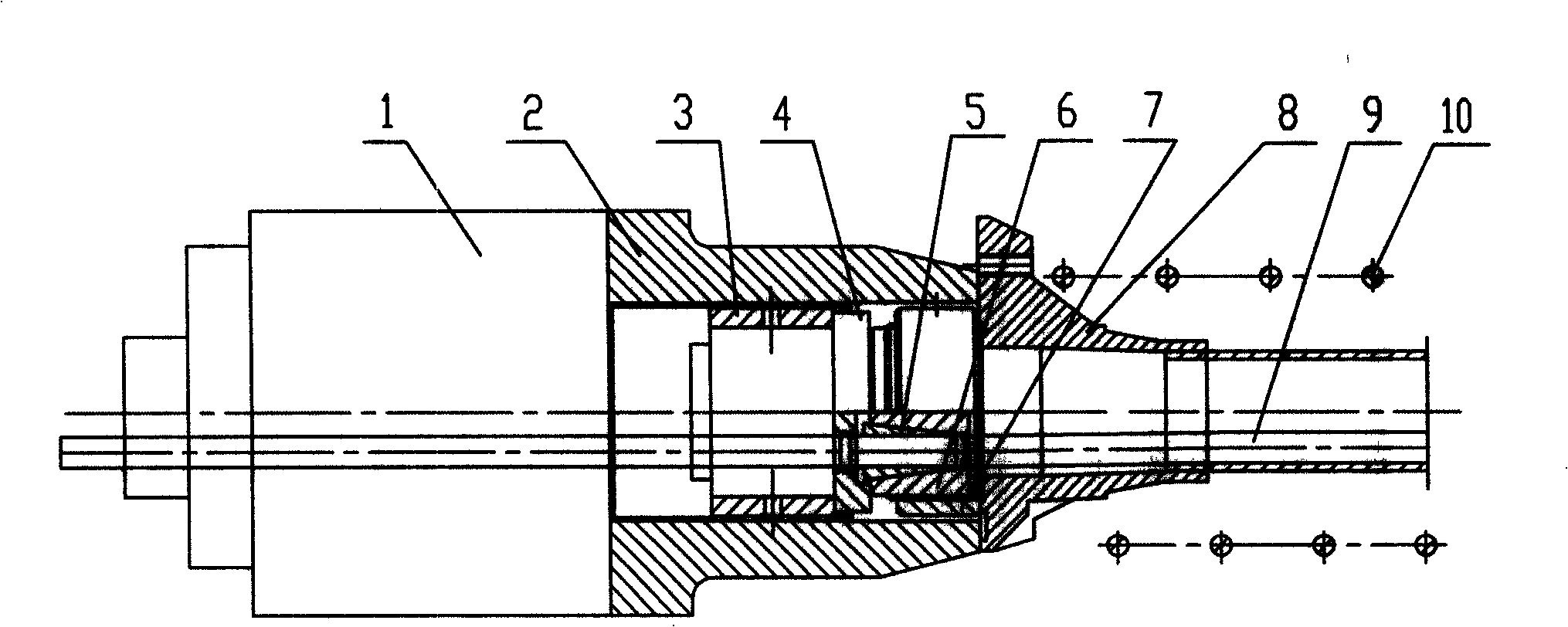
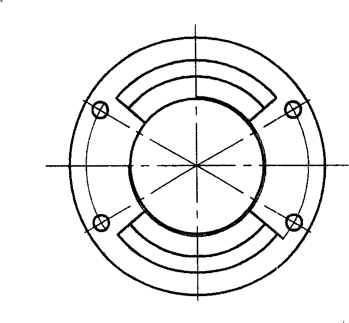
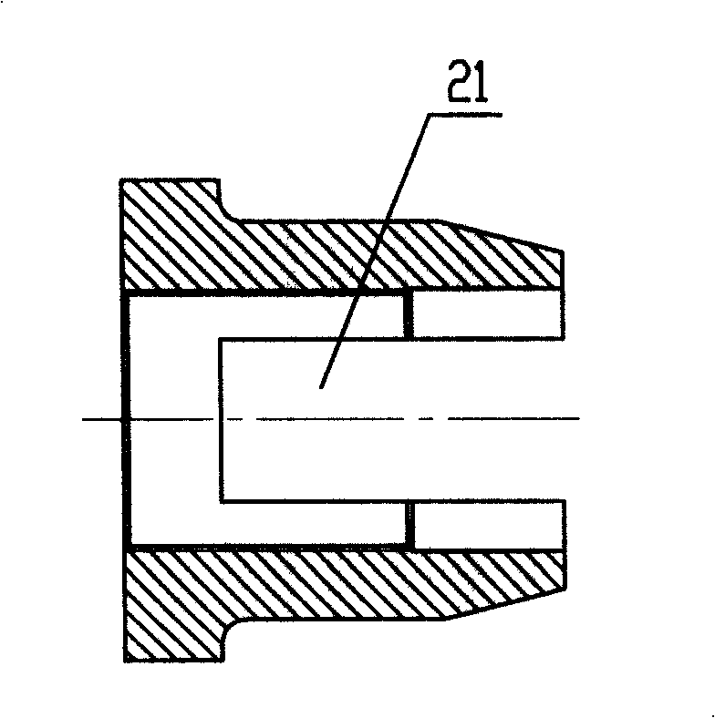
[0016] A short-bundle steel strand tension limiting device is composed of a supporting leg 2, a supporting nut 3 and a limiting plate 4. The supporting leg 2 is a steel cylinder with two symmetrical windows 21. With internal thread, the support nut 3 located in the support leg is a section of steel ring, and four through holes 31 for adjusting the position of the support nut 3 are evenly distributed on the center circumference. The support nut 3 is also provided with an inner part on the support leg. The external thread that matches the thread is connected with the support foot 2. The limit plate 4 is a flat cylindrical steel plate with a through hole 41 for passing the steel strand evenly distributed in the middle and a concave step 42 at the end. The number of through holes 41 on the position plate 4 is the same as the number of clip holes on the anchor plate of the anchor assembly to be stretched. The limit plate 4 is located in the supporting leg 2 and adjacent to the supporti...

Embodiment 2

[0020] The method of using the short-stranded steel strand tension limit device for tension and anchoring.

[0021] Using the short-bundle steel strand tensioning and limiting device composed of the supporting legs 2, the supporting nut 3 and the limiting plate 4 described in the first embodiment, the components to be tensioned are mainly composed of the clip 5, the anchor plate 6, and the anchor nut 7. Anchor backing plate 8 and steel stranded wire 9 are formed. One end of the supporting leg 2 of the short-stranded steel strand tension limit device is supported on the anchor backing plate 8, and the other end is connected to the jack 1 by bolts, and the supporting nut is adjusted. The position of 3 realizes the operation of the first tension and the second tension: during the first tension, the supporting nut 3 against the limit plate 4 makes the anchor plate 6 close to the end surface of the anchor pad 8, and the first tension When anchoring, the steel strand 9 is restricted and...


PUM


Abstract

The invention relates to short steel strand stretching caging device and a method used for stretching and anchoring. The caging device consists of an arm brace, a supporting nut and a limited plate, wherein, the arm brace is a cylinder which is provided with two symmetrical windows and internal threads; the supporting nut which is positioned in the arm brace is a section of circular ring the central circumference of which is uniformly distributed with 1 to 8 through holes which are used for adjusting positions; external threads which are matched with the internal threads on the arm brace are arranged on the supporting nut which is connected with the arm brace through the external threads; the limited plate is a flat cylindrical plate the central part of which is uniformly provided with through holes used for steel strands to pass through and the end part of which is provided with a concave step; the number of the through holes on the limited plate is consistent with that of clamping piece holes on an archor plate of an archor component to be stretched; and the limited plate is positioned inside the arm brace and adjacent to the supporting nut. Under the condition of stretching, the arm brace of the stretching caging device is connected with a jack through bolts and the operations of primary stretching and secondary stretching can be realized by adjustment of the position of the supporting nut without replacement of the jack, thereby the structure of the device is simple and the construction method is convenient.

Description

Technical field: [0001] The invention relates to an auxiliary tensioning tool for prestressed tendons and a tensioning method thereof, in particular to a short-stranded strand tensioning limit device and a method for tensioning and anchoring. Background technique: [0002] At present, more and more bridges use steel strand anchoring systems as vertical prestressing. The vertical prestressing tendons in bridges are generally short. The contraction of the steel strands during tension and anchorage of conventional anchors is generally 4 ~7mm, which makes the remaining effective prestress of the steel strands too low and uncertain, unable to meet the design requirements of vertical prestress. In order to meet the design requirements of vertical prestress, it is necessary to change the structure and tensioning method of conventional anchors. On the structure, the outer circle of the anchor plate is threaded and a nut is added; the tensioning method is now mostly used for secondary ten...

Claims


Application Information

Patent Timeline
Patent Type & Authority Applications(China)
IPC IPC(8): E04G21/12E04C5/12E01D21/00
Inventor 苏强黄颖朱万旭龙跃陆明俊
Owner LIUZHOU OVM MASCH CO LTD
Why Eureka
Try Eureka