
Engine cylinder lid burning compartment structure

An engine cylinder and combustion chamber technology, applied in engine components, combustion engines, machines/engines, etc., can solve the problems of heat transfer, poor thermal conductivity, and high NOx

Inactive Publication Date: 2008-09-10
LONCIN MOTOR
View PDF0 Cites 1 Cited by
  • Summary
  • Abstract
  • Description
  • Claims
  • Application Information

AI Technical Summary

Problems solved by technology

Judging from the structure of the combustion chamber on the existing engine cylinder head, there is a sharp corner transition between the outer periphery of the combustion chamber wall and the end surface of the cylinder head. Through heat flow analysis, it is found that when the combustion chamber conducts heat, it is easy to form a dead angle around the circumference, making this place The heat transfer and heat conduction effect of the combustion chamber is not good, the temperature of the surrounding area of ​​the combustion chamber is too high, and the surface is hot, which leads to the high content of NOx in the engine exhaust emission.

Method used


Image

  • Engine cylinder lid burning compartment structure
  • Engine cylinder lid burning compartment structure
  • Engine cylinder lid burning compartment structure

Examples


Embodiment Construction

[0013] Below in conjunction with accompanying drawing and embodiment the present invention will be further described:

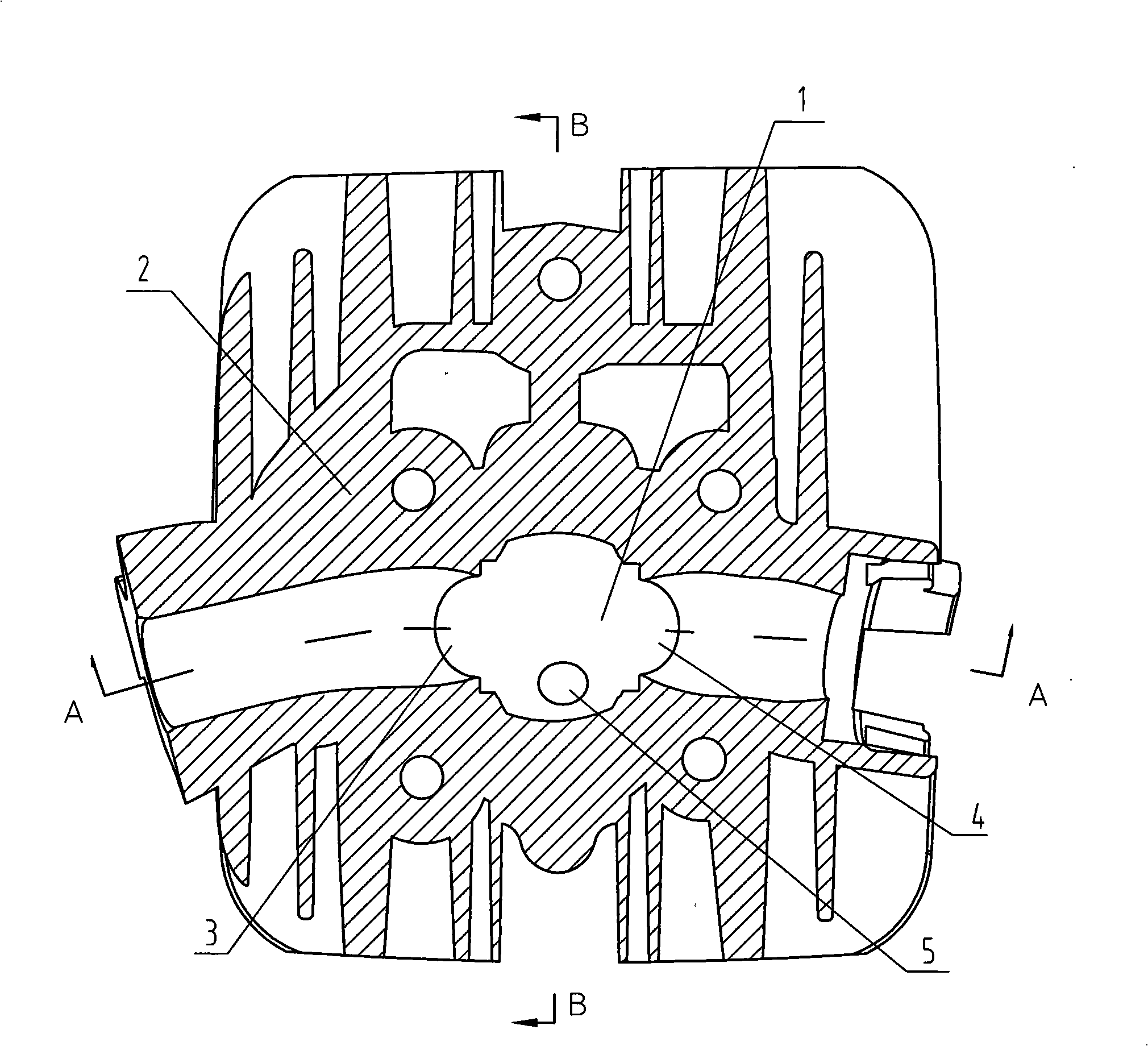
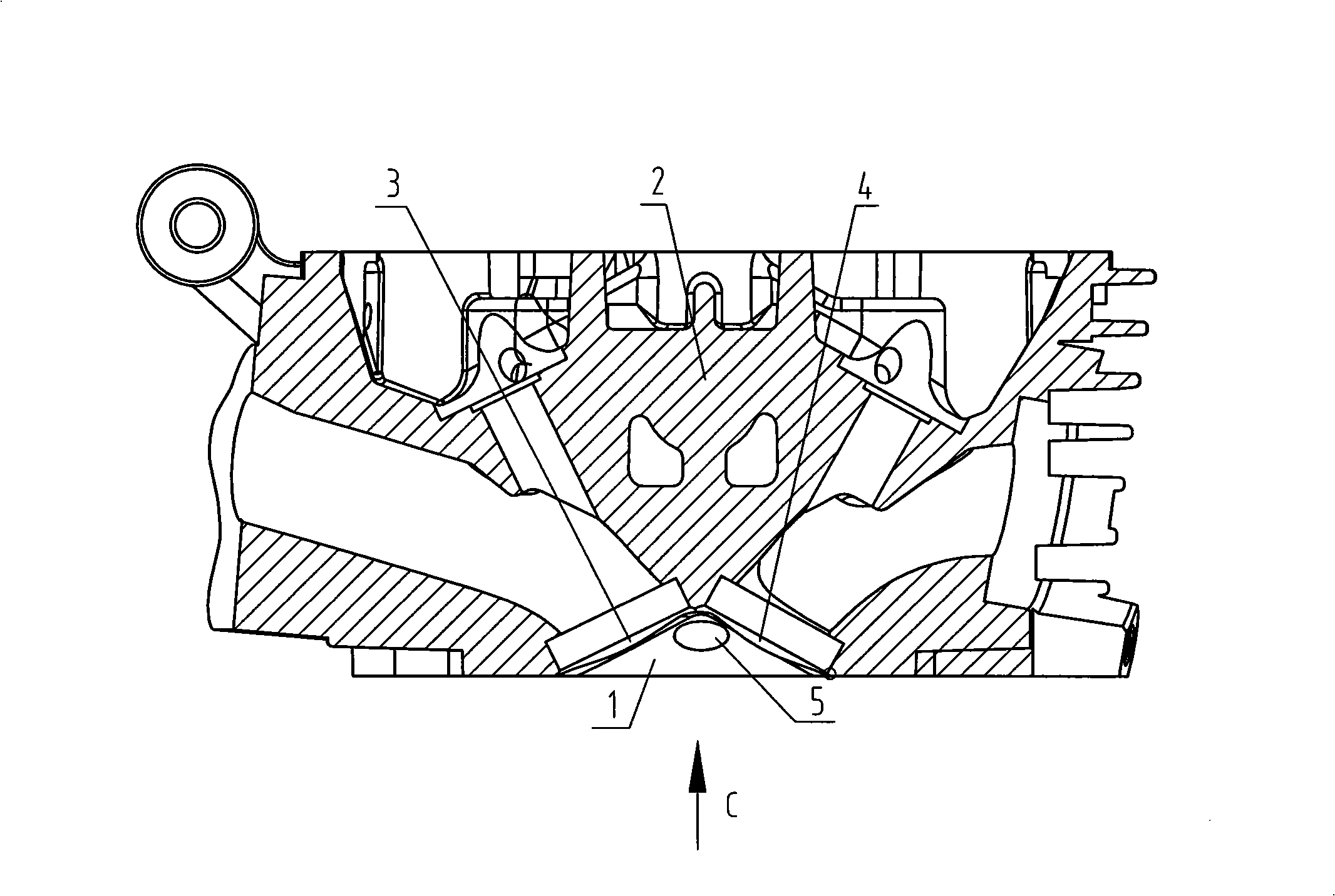
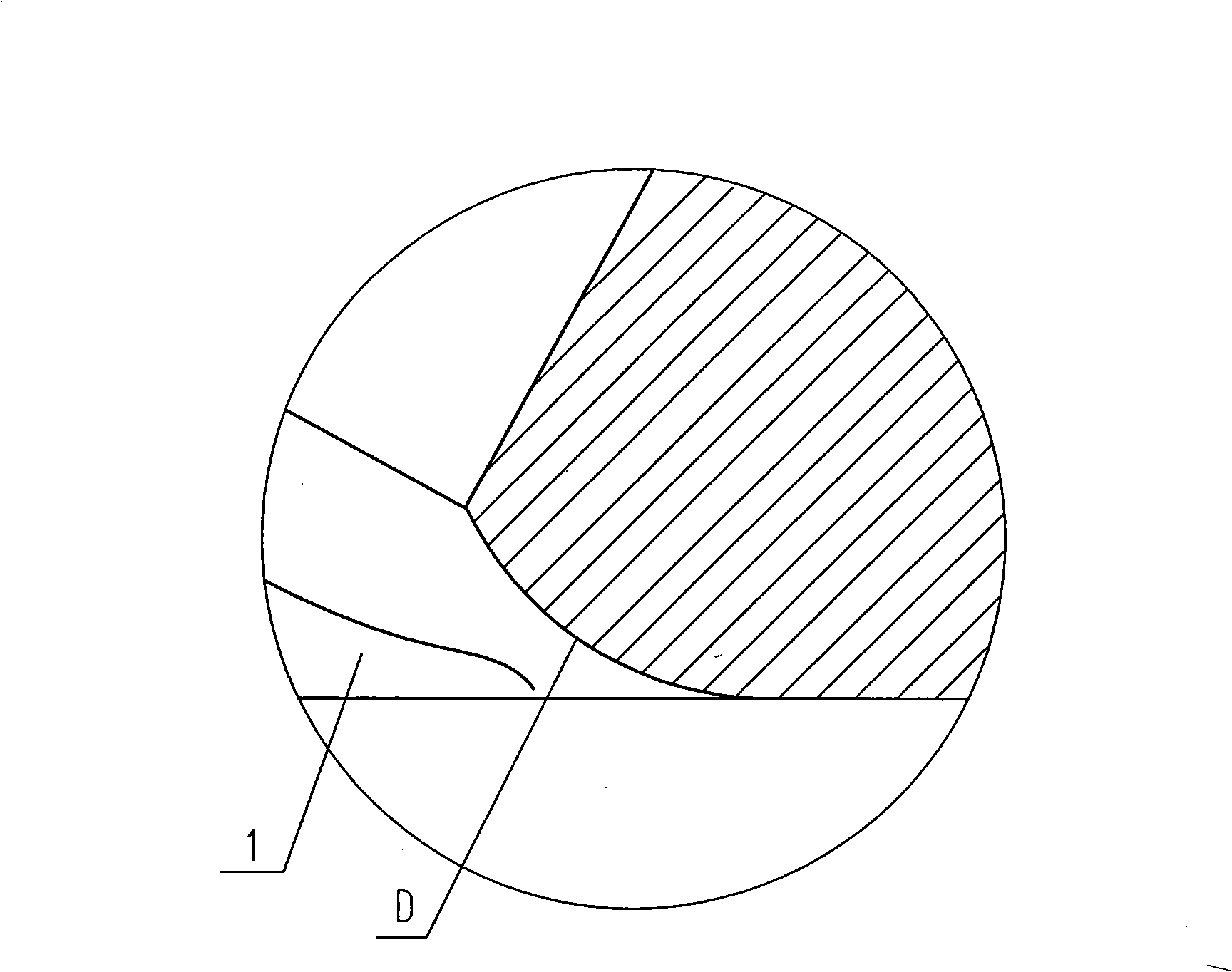
[0014] Such as Figure 1 to Figure 5 As shown, the structure of the combustion chamber on the engine cylinder head of the present invention is: the combustion chamber 1 is in the shape of a pit on the cylinder head 2, and the wall of the combustion chamber 1 is provided with inlet and exhaust valve seat mounting holes 3,4 And the spark plug mounting hole 5, D between the outer peripheral edge of the combustion chamber 1 wall and the end face of the cylinder head 2 is a circular arc R transition or a smooth transition.

[0015] After adopting the above structure, the sharp angle between the outer peripheral edge of the combustion chamber 1 wall and the end surface of the cylinder head 2 is eliminated, so that no dead angle will be formed at the outer peripheral edge of the combustion chamber 1 wall during heat conduction, so that the heat conduction is smooth....


PUM


Abstract

The invention provides a structure of a combustion chamber on a cylinder cover of an engine, wherein, the combustion chamber has a pit shape on the cylinder cover; a mounting hole of an intake valve seat insert, a mounting hole of an exhaust valve seat insert and a mounting hole of a spark plug are arranged on the wall of the combustion chamber; arc R transition or smooth transition is performed between the periphery of the wall of the combustion chamber and the end face of the cylinder cover. Compared with the prior similar engines, the engine adopting the technical proposal of the invention prevents the phenomenon of ultrahigh temperature on the periphery of the wall of the combustion chamber, so that the content of Nox in emitted tail gas of the engine can be reduced by 10 to 20 percent.

Description

technical field [0001] The invention belongs to the technical field of engines, and in particular relates to an improved design of a combustion chamber structure on an engine cylinder head. Background technique [0002] When the engine is working, the piston reciprocates in the cylinder. When the piston is at the top dead center, the space formed by the top of the piston and the inner surface of the cylinder head is called the combustion chamber. Most of the direct-injection combustion chambers (also known as unified combustion chambers) appear on the piston or cylinder head in the form of pits. [0003] At present, the combustion chambers in the form of dimples on the engine cylinder head include bathtub type, wedge type, hemispherical type, etc., among which the hemispherical type is in the majority. After the mixed gas enters the combustion chamber, it is compressed and burned to do work and then discharged. Due to the effect of high temperature and high pressure, the ox...

Claims


Application Information

Patent Timeline
Patent Type & Authority Applications(China)
IPC IPC(8): F02F1/24
CPCF01L3/22F02B23/08F02F1/24F02F1/30Y02T10/12
Inventor 秦元伟顾品胜
Owner LONCIN MOTOR
Learn More