Hydrogen engines and its burnt gas jet method

An engine and gas technology, applied in the direction of engine components, combustion engines, machines/engines, etc., can solve the problems of low gas charging efficiency and thermal efficiency of hydrogen engines, early combustion and tempering of carburetor engines, insufficient output power, etc., to achieve Solve the problems of early ignition and flashback, improve combustion and reduce emissions

Active Publication Date: 2011-07-13
CHERY AUTOMOBILE CO LTD
View PDF0 Cites 3 Cited by
  • Summary
  • Abstract
  • Description
  • Claims
  • Application Information

AI Technical Summary

Problems solved by technology

For hydrogen engines, delivering fuel through a carburetor is the simplest fuel supply method, but carburetor engines are prone to abnormal combustion such as early ignition and flashback
Gas and air are mixed in the air passage and then enter the cylinder, resulting in low charging efficiency and thermal efficiency of the hydrogen engine, and insufficient output power
In addition, there will be an increase in emissions

Method used


Image

  • Hydrogen engines and its burnt gas jet method
  • Hydrogen engines and its burnt gas jet method

Examples


Embodiment 1

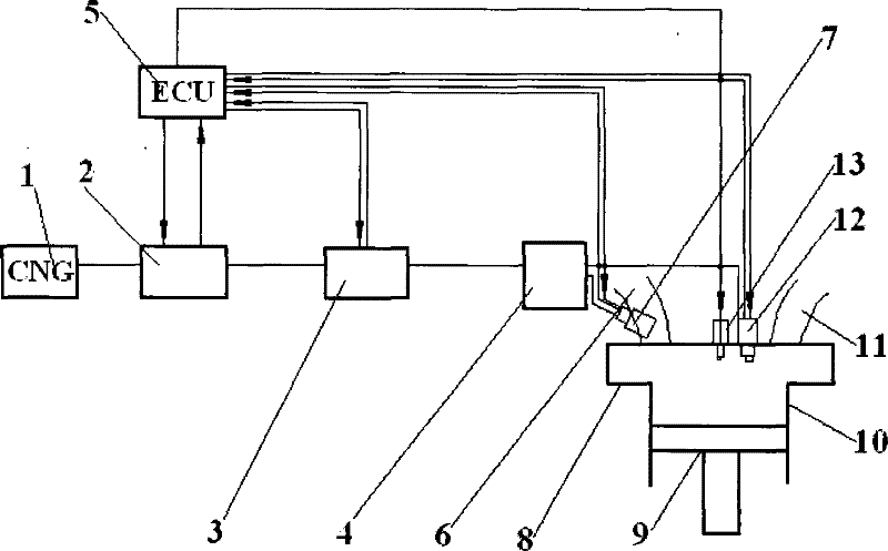
[0029] The gas injector described in the above technique includes the external mixing gas injector 7 for indirect injection and the internal mixing gas injector 12 for direct injection.

[0030] Direct injection and indirect injection are achieved with these two different gas injectors. And according to the needs of the actual working conditions, the corresponding gas injectors are controlled to perform gas injection under different conditions, or to stop the injection. The combination of the two gas injectors achieves the purpose of the invention.

Embodiment 2

[0032] The structure and installation method of the external mixed gas injector 7 described in the first embodiment is that the connection port of the intake manifold 6 and the cylinder head 8 communicates with the cylinder 10 .

[0033] External mixed gas injector 7 can use 3.5bar KEIHIN second generation CNG injector to achieve injection. The external mixing gas injector 7 mixes the hydrogen gas in the intake port and indirectly injects it into the cylinder 10 .

Embodiment 3

[0035] The structural installation method of the internal mixed gas injector 12 described in the first embodiment is that it communicates with the cylinder 10 directly through the cylinder head 8 , and is located in the center of the cylinder head 8 next to the CNG-specific spark plug 13 .

[0036] The internal mixing gas injector 12 injects hydrogen directly into the cylinder. Since the internal mixed gas injector 12 located in the center of the cylinder directly injects near the CNG dedicated spark plug 13 (between the intake valve and the exhaust valve), the charging efficiency is improved and the power of the engine is increased.


PUM


Abstract

The invention discloses a hydrogen engine, which comprises a fuel gas supply system, an intake manifold, a CNG special spark plug and a cylinder, wherein, fuel gas injectors are arranged on different positions of the end part of the fuel gas supply system extending into a cylinder cover of the engine; and hydrogen is directly injected into the cylinder of the engine through the fuel gas injector or is indirectly injected into the cylinder of the engine through the fuel gas injector after mixing with inlet gas in an inlet channel. By adoption of the technical proposal, direct injection of hydrogen in the cylinder of the engine is realized; compared with a general hydrogen engine, higher charging efficiency and thermal efficiency are obtained by adoption of higher compression ratio, and thepower and the torque of the engine are increased; moreover, the hydrogen engine has the advantages of high power output, high response speed and so on; simultaneously, the combustion is improved and the exhaust is reduced. The problems of premature combustion and backfire are solved by adoption of the control means of combination of direct injection in the cylinder and indirect injection of the inlet channel, and simultaneously the maximum potential and exhaust advantages of hydrogen engines are given full play.

Description

technical field [0001] The present invention belongs to the technical field of automobile structure, and relates to automobile engines, more particularly, the present invention relates to a hydrogen engine. In addition, the present invention also relates to a gas injection method used in such a hydrogen engine. Background technique [0002] At present, hydrogen engines on the market generally use an external method to form a mixture, usually using a carburetor, intake manifold injection, and intake port injection to form a mixture. For a hydrogen engine, delivering fuel through a carburetor is the simplest fuel supply method, but a carburetor engine is prone to abnormal combustion such as pre-ignition and flashback. The gas and air are mixed in the air passage and then enter the cylinder, resulting in low charging efficiency and thermal efficiency of the hydrogen engine, and insufficient output power. In addition, it will cause an increase in emissions. SUMMARY OF THE IN...

Claims


Application Information

Patent Timeline
Patent Type & Authority Patents(China)
IPC IPC(8): F02M21/02
CPCY02T10/32Y02T10/30
Inventor 黄国媛
Owner CHERY AUTOMOBILE CO LTD
Why Eureka
Try Eureka