Connector for close type compressor and operating fluid inhalation device using same

A closed compressor and working fluid technology, which is applied in the direction of machines/engines, liquid variable displacement machines, mechanical equipment, etc., can solve the problems of slender closed container 8 and reduce the fluidity of working fluid, and achieve the goal of improving fluidity Effect

Inactive Publication Date: 2008-09-10
LG ELECTRONICS INC
View PDF0 Cites 3 Cited by
  • Summary
  • Abstract
  • Description
  • Claims
  • Application Information

AI Technical Summary

Problems solved by technology

[0007] The first problem is that although the bellows type connector 6 is in close contact with the inner surface of the closed container 8, large unevenness is formed on the passage where the working fluid flows, thereby reducing the fluidity of the working fluid.
[0008] The second problem is that the connector 6 is installed to protrude towards the inner surface of the closed container 8, which faces the front surface of the cylinder on which the air inlet muffler 1 is installed, that is, the connector 6 is installed on the air inlet muffler. The front of the device 1, thus closing the container 8 is slender in this direction

Method used


Image

  • Connector for close type compressor and operating fluid inhalation device using same
  • Connector for close type compressor and operating fluid inhalation device using same
  • Connector for close type compressor and operating fluid inhalation device using same

Examples


Embodiment Construction

[0029] Preferred embodiments of the present invention will be described below with reference to the accompanying drawings. In the following description and drawings, the same or similar components are denoted by the same reference numerals, and thus repeated descriptions of the same or similar components will be omitted.

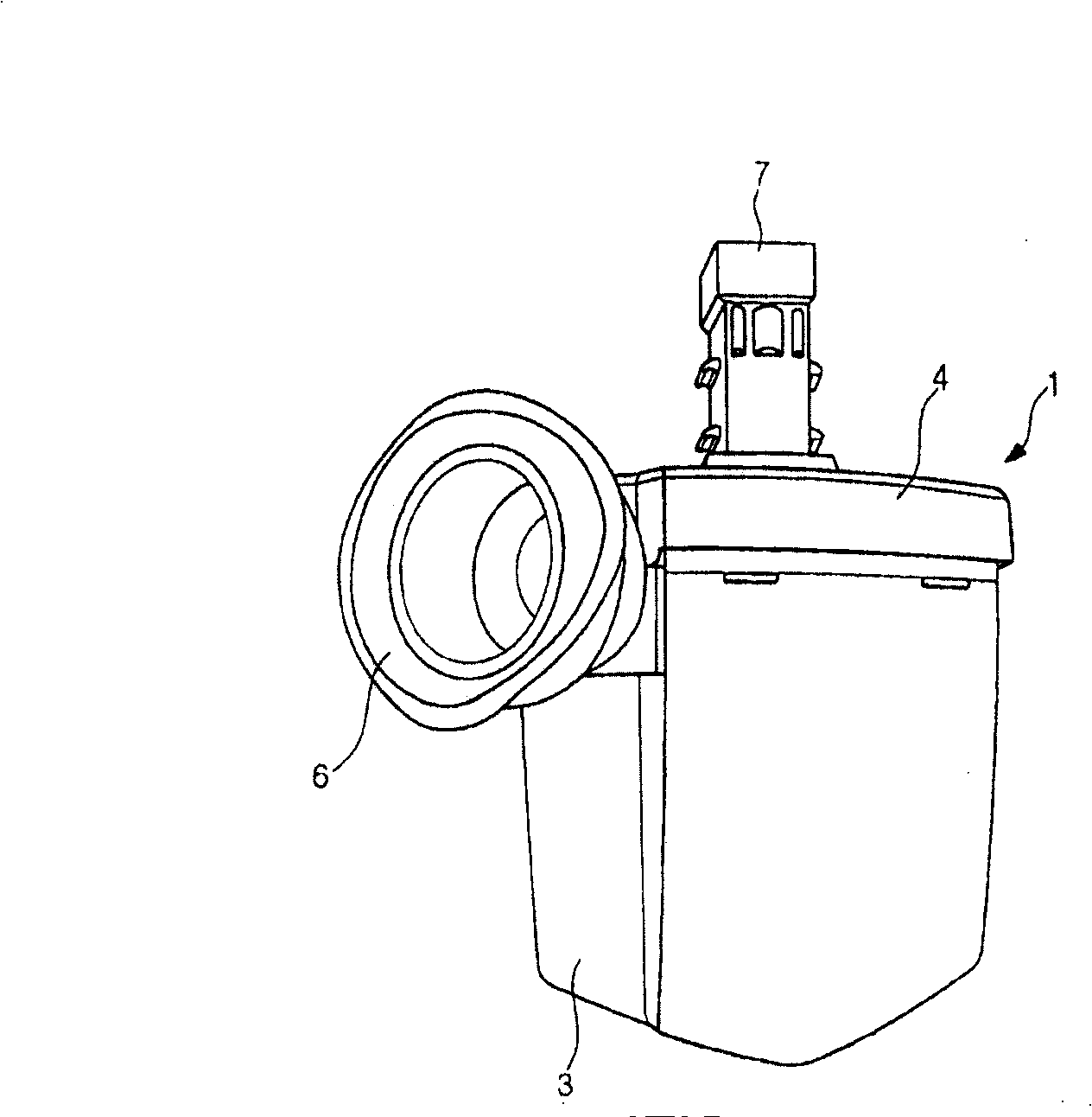
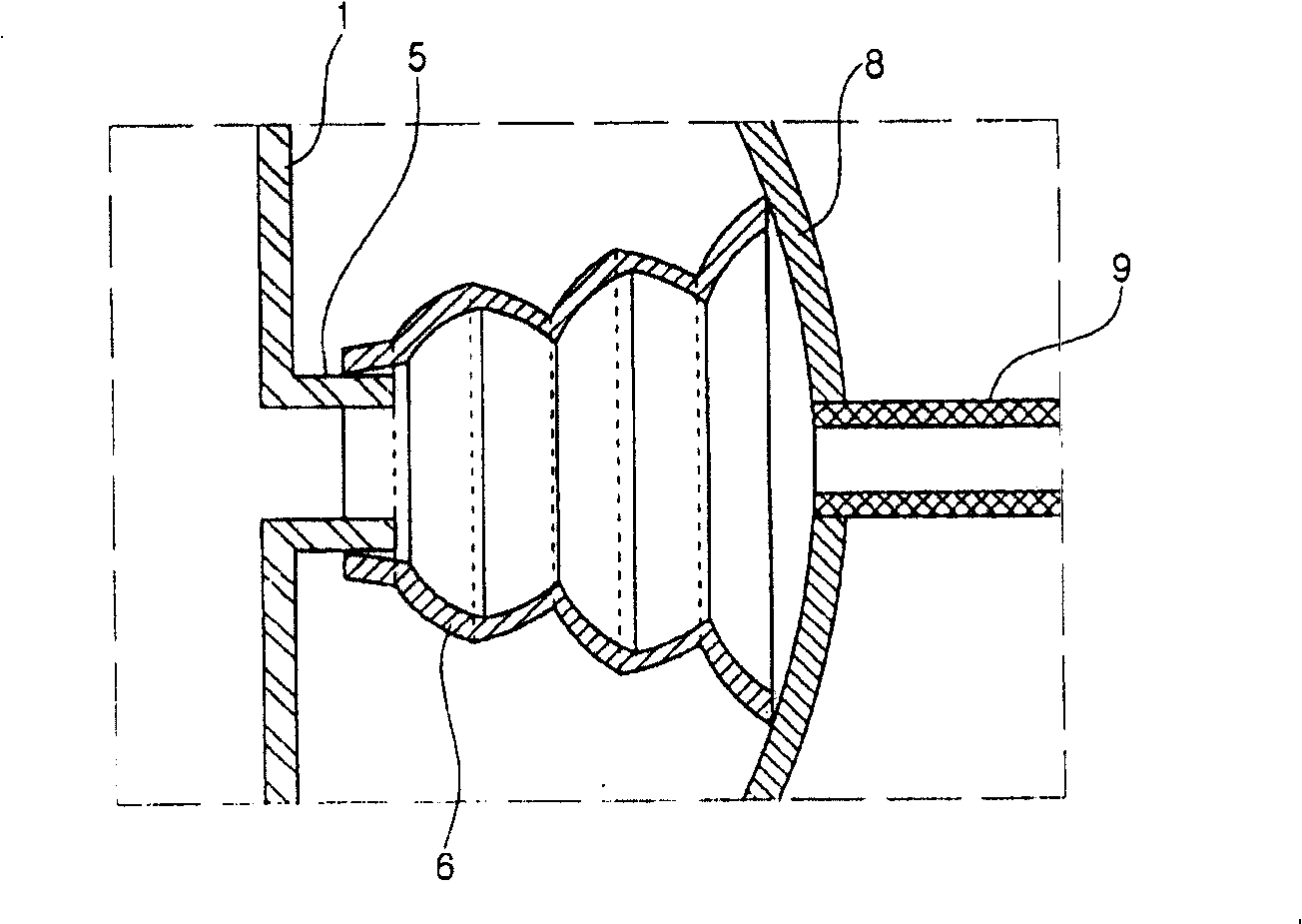
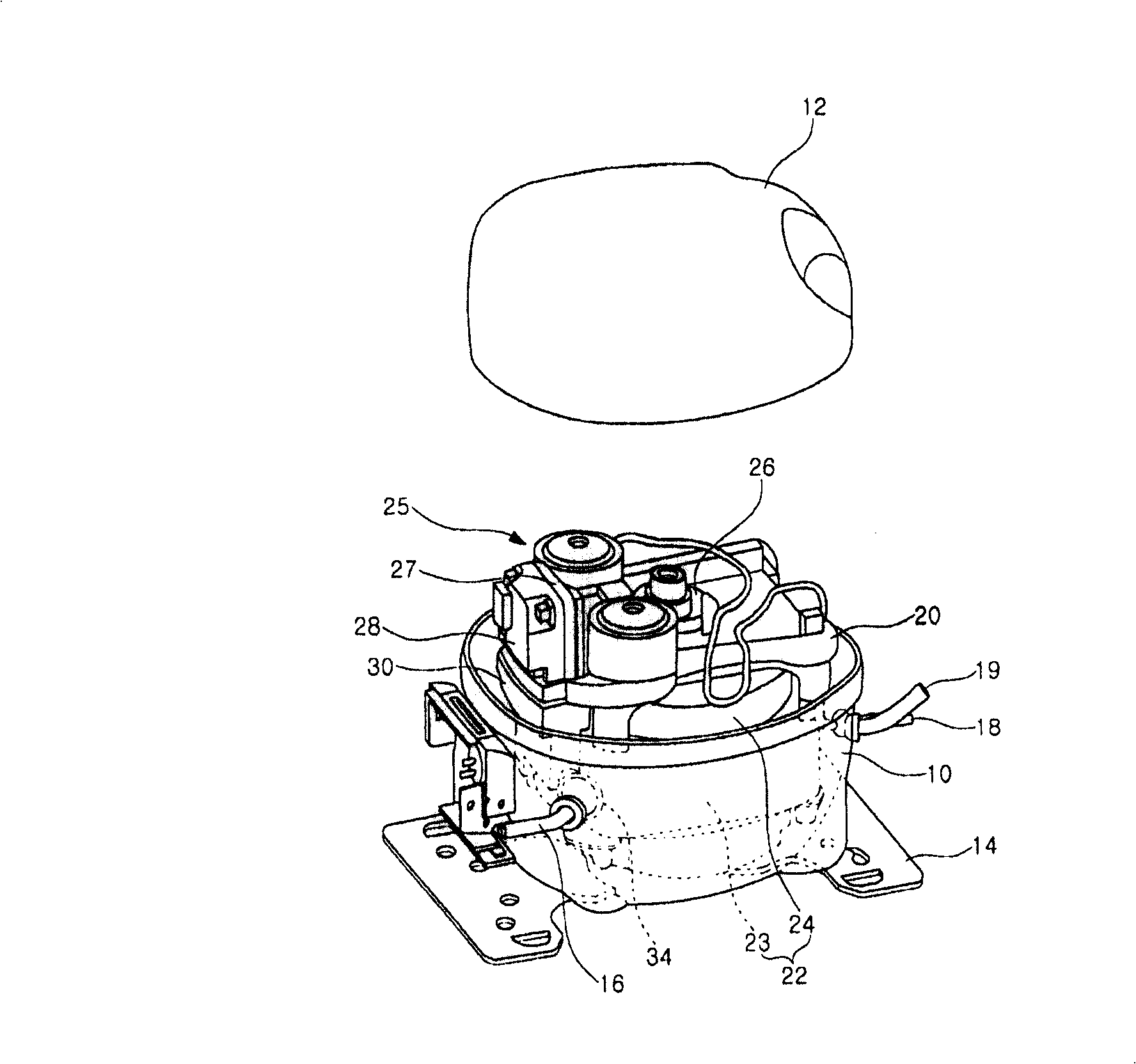
[0030] image 3 is an exploded perspective view of a hermetic compressor using a working fluid suction device according to a preferred embodiment of the present invention, FIG. 4 is a partial sectional view of the configuration of an embodiment of the present invention, and FIG. 5 is a perspective view Fig. 1 shows the intake muffler and connectors constituting this embodiment of the present invention.

[0031] Referring to these drawings, the appearance of the compressor is composed of a lower container 10 and an upper container 12 . The lower container 10 and the upper container 12 are engaged with each other to form a closed space therebetween. Each of...


PUM


Abstract

The invention discloses a connector used for a closed type compressor and a working fluid suction device using the connector. The closed type compressor comprises a suction pipe (16) and a suction silencer (30), wherein, the suction pipe (16) is connected to a closed container so as to conveniently convey working fluid into the closed container; and the suction silencer (30) optimizes the working fluid which is led in through the suction pipe (16), conveys the working fluid to a compression chamber and then eliminates the noise. The connector comprises a connector pipe (35), an enlarged diameter pipe (36) and a contact skirt part (37), wherein, the connector pipe (35) is communicated with the suction pipe (16) and the suction silencer (30) so as to convey the working fluid through the suction silencer (30) and is connected with a communicating pipe (33) which is formed on one surface of the suction silencer (30); the enlarged diameter pipe (36) has enlarged diameter and extends towards the suction pipe (16) from the connector pipe (35); a central line of the enlarged diameter pipe (36) is intersected with a central line of the connector pipe (35) at a certain angle; the contact skirt part (37) is significantly enlarged from the front end of the enlarged diameter pipe (36); and the inner surface of the contact skirt part (37) closely contacts the inner surface of the closed container. Therefore, the working fluid flows smoothly in the suction silencer without leakage; the fluidity of the working fluid in the connector is improved, and the suction device dose not occupies much internal space of the closed container.

Description

technical field [0001] The present invention relates to hermetic compressors, and more particularly to a connector for a hermetic compressor and a working fluid suction device using the same, which connector optimizes flow into the compressor, into the compression chamber of the compressor and is drawn The working fluid sucked into the air-intake muffler to eliminate the noise generated from the compression chamber. Background technique [0002] figure 1 shows the appearance of the air inlet muffler according to the prior art, while figure 2 A working fluid suction device according to the prior art is shown. In these figure 1 and 2 Among them, the air intake muffler 1 includes an upper body 4 and a lower body 3 provided therein with a space through which a working fluid flows and noise is eliminated. [0003] Arranged on one side of the upper body 4 or the lower body 3 is a communication pipe 5 communicating with the inside and outside of the body, to which a connector...

Claims


Application Information

Patent Timeline
Patent Type & Authority Applications(China)
IPC IPC(8): F04B39/12
Inventor 郑珉圭
Owner LG ELECTRONICS INC
Why Eureka
Try Eureka