Servo controller

A servo control device and learning control technology, which is applied in the direction of program control, digital control, thread cutting device, etc., can solve the problems of the deterioration of the servo characteristics of the rotating shaft, large synchronization errors, and failure to obtain learning effects

Inactive Publication Date: 2008-09-10
FANUC LTD
View PDF2 Cites 44 Cited by
  • Summary
  • Abstract
  • Description
  • Claims
  • Application Information

AI Technical Summary

Problems solved by technology

[0008] In external thread or internal thread processing, if the synchronously controlled multiple drive sources have the same servo characteristics, the rotary axis and the feed axis have the same position deviation, theoretically no synchronization error will occur, but with the rotation axis Higher rigidity increases the inertia of the rotary axis, or when the rotary axis rotates at high speed, the servo characteristics of the rotary axis will deteriorate compared with the feed axis, and a large positional deviation may occur when the rotary axis accelerates and decelerates
Although such a synchronization error can be gradually converged to a small value through learning control, it is necessary to repeat the same position command to exert the learning effect of learning control, so there is a problem that cannot be obtained in the first control. learning effect, resulting in a large synchronization error

Method used


Image

  • Servo controller
  • Servo controller
  • Servo controller

Examples


Embodiment Construction

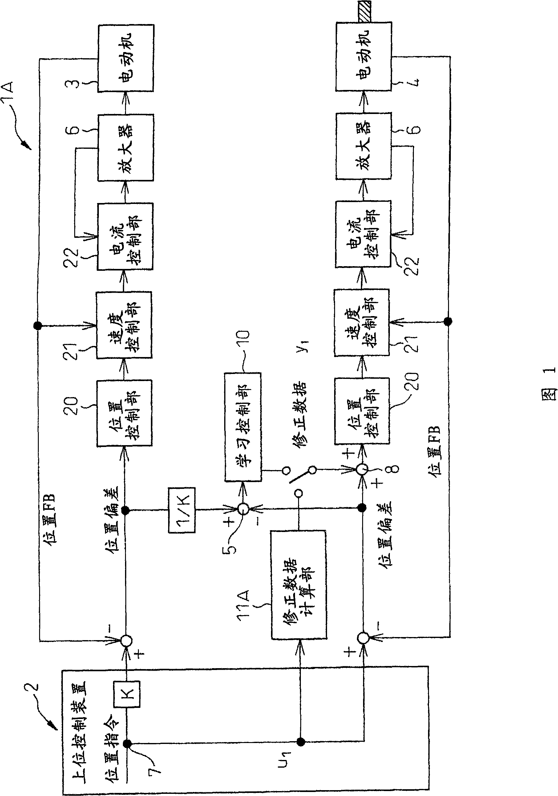
[0035] Hereinafter, specific examples of embodiments of the present invention will be described using the drawings. FIG. 1 is a block diagram of a first embodiment of the servo control device of the present invention. The servo control device 1A of the present embodiment is connected to the host control device 2 via a common memory not shown. The movement command value output from the host control device 2 is input to the servo control device, and the spindle motor (master servo motor) 3 that drives the machine tool spindle (master shaft) and the feed side that drives the slave shaft that performs direct motion are synchronously controlled. Command value of the servo motor (slave side servo motor) 4. The position deviation is obtained by subtracting the position feedback value from the position detector (not shown) from the position command value. The position detector is used to detect the position of the servo motors 3 and 4 and is installed in the servo motors 3 and 4 . O...


PUM


Abstract

A servo controller for synchronously controlling a master driving source for driving a driving shaft and a slave driving source for driving a driven shaft, having a position control section that performs a position control based on a positional deviation which is a difference between a position command value given to the slave driving source and a feedback value detected from the slave driving source, an operational section that calculates a synchronization error which is a difference of the positional deviation between the master driving source and the slave driving source, and a correction data calculating section that calculates first correction data for correcting the positional deviation of the slave driving source.

Description

[0001] Cross References to Related Art [0002] This application is based on and enjoys the benefit of priority of Japanese Patent Application No. 2007-058442 previously filed on March 8, 2007; the entire contents of which are incorporated herein by reference. technical field [0003] The present invention relates to a servo control device, which is used for machine tools, robots, presses, injection molding machines, etc. that process workpieces, and is used for synchronizing the driving source on the driving side and the driving source on the driven side , such as a machine that repeatedly performs the same processing on a workpiece, such as thread processing or tap processing. Background technique [0004] Generally, when machining external threads on the outer peripheral surface of a workpiece, the workpiece clamped by a spindle or the like is rotated, a predetermined amount of cutting is given to the thread cutting tool, and the cutting tool is linearly moved relative to...

Claims


Application Information

Patent Timeline
Patent Type & Authority Applications(China)
IPC IPC(8): G05B19/19B23G1/16
CPCG05B2219/42141G05B2219/45216G05B2219/45214G05B19/19G05B2219/50234G05B2219/42186G05B2219/42249
Inventor 前田和臣园田直人丰泽雪雄
Owner FANUC LTD
Why Eureka
Try Eureka