
A method to increase production rate of a continuous mixer or extruder

A technology of mixer and extruder, which is applied in the field of continuous mixer or extruder for processing, and can solve problems such as difficulty in temperature control.

Inactive Publication Date: 2008-09-10
UNIVATION TECH LLC
View PDF2 Cites 2 Cited by
  • Summary
  • Abstract
  • Description
  • Claims
  • Application Information

AI Technical Summary

Problems solved by technology

For this reason, temperature control is difficult to achieve once the polymer is melted

Method used


Image

  • A method to increase production rate of a continuous mixer or extruder

Examples


Embodiment

[0016] In the following examples, melt index (MI) was measured by ASTM-D1238 and density was measured by ASTM D-792 at 190°C and 2.16 kg.

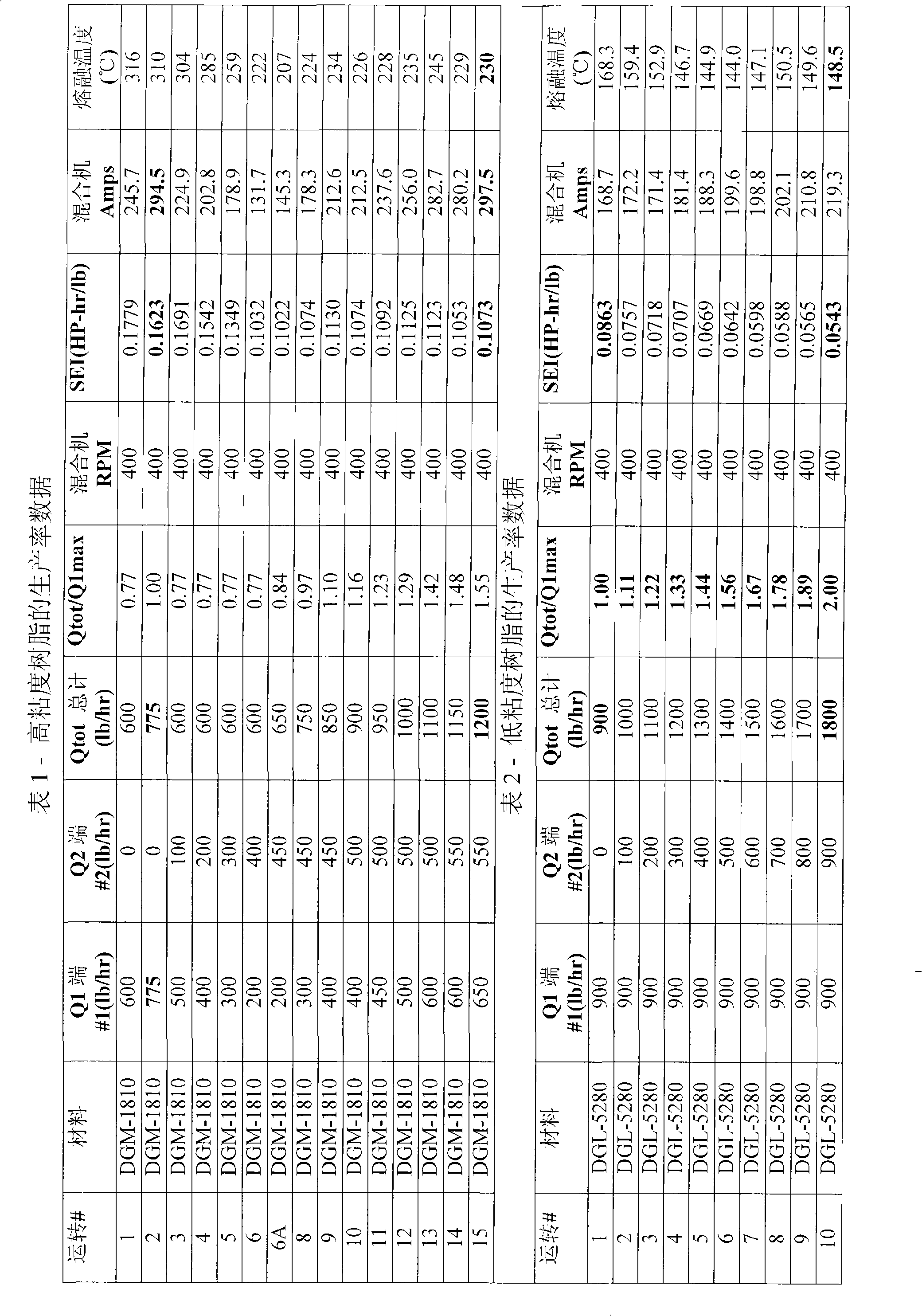
[0017] The concept of the present invention is in a two-stage Farrel TM Tests were carried out on a mixer, where the vented end was used as the second feed end, resulting in the results shown in Tables 1 and 2. In a two-stage Farrel with two feed ends and a two-stage mixing rotor TM 4”FCM TMexperiment on. Each rotor has a first stage comprising an auger feed section followed by a mixing section. The second stage is the second stage portion of the rotor which was originally designed to improve ventilation and degassing and to improve additional mixing prior to polymer discharge.

[0018] As shown in Table 1, for high viscosity resin (DGM-1810 polyethylene (density 0.918g / cm 3 , MI is 1.0g / 10min, melting point is 121.2°C)) - this is a representative intermediate gas phase resin - when using a single feed end, the maximum production rat...


PUM

PropertyMeasurementUnit
densityaaaaaaaaaa
densityaaaaaaaaaa

Abstract

Compounding or extrusion rates can be increased by splitting the polymer solid feed. Melting of additional solid polymer is significantly assisted by excess enthalpy from incoming melt from a primary mixing stage. Depending on resin rheology and melting characteristics, rate increases were achieved of from up to about 55 to about 100% rate increase over the use of a single feed at the same rotor speed. The net result is a decrease in the overall SEI (specific energy input to the polymer) and thus melt temperatures.

Description

technical field [0001] The present invention relates to processing with continuous mixers or extruders, and more particularly to increasing the production rate of such continuous mixers or extruders. Background technique [0002] The throughput of extrusion or compounding lines is often limited by the capacity of the extruder or continuous mixer. Solid fed continuous mixers and extruders are usually run at partial capacity and rarely up to the volumetric melt pumping capacity of the screw. Production rates are usually limited by machine power, solids feed related issues, product quality, or a combination thereof (assuming auxiliary equipment is adequate). For example, the throughput of resins with high melt viscosity is typically limited by machine power. In contrast, the productivity of resins with low melt viscosity is typically limited by issues related to solids transport. In some cases, such as in reactive extrusion and compounding, product quality can also limit pro...

Claims


Application Information

Patent Timeline
Patent Type & Authority Applications(China)
IPC IPC(8): B29C47/10B29C48/03B29C48/285B29C48/395
CPCB29C47/0009B29C47/1081B29C47/10B29C47/585B29C47/1027B29C48/288B29C48/297B29C48/03B29C48/285B29C48/501
Inventor M·埃塞格A·C·纽鲍尔A·哈拉齐A·A·夸兰塔
Owner UNIVATION TECH LLC
Learn More