Multi-point synchronization lifting mechanism composed of steel wire flexible shaft

A technology of steel wire flexible shaft and synchronous lifting, applied in the direction of hoisting devices, etc., can solve the problems of high cost, low synchronization precision, and complexity, and achieve the effect of low cost, high precision, and small mechanical vibration

Inactive Publication Date: 2008-09-17
48TH RES INST OF CHINA ELECTRONICS TECH GROUP CORP
View PDF0 Cites 7 Cited by
  • Summary
  • Abstract
  • Description
  • Claims
  • Application Information

AI Technical Summary

Problems solved by technology

[0004] The technical problem to be solved by the present invention is to propose a multi-point synchronous lifting mechanism composed of flexible steel wire shafts, which has high synchronization accuracy, simple structure, It has the advantages of low cost, high reliability, low noise, convenient speed regulation, simple installation, and convenient maintenance. It can meet the requirements of polysilicon ingot casting furnaces for high-precision synchronous motion, and can also be used for lifting and synchronous motion of large equipment (such as large Boiler upper and lower furnace cover opening, lifting platform, etc.)

Method used


Image

  • Multi-point synchronization lifting mechanism composed of steel wire flexible shaft
  • Multi-point synchronization lifting mechanism composed of steel wire flexible shaft
  • Multi-point synchronization lifting mechanism composed of steel wire flexible shaft

Examples


Embodiment Construction

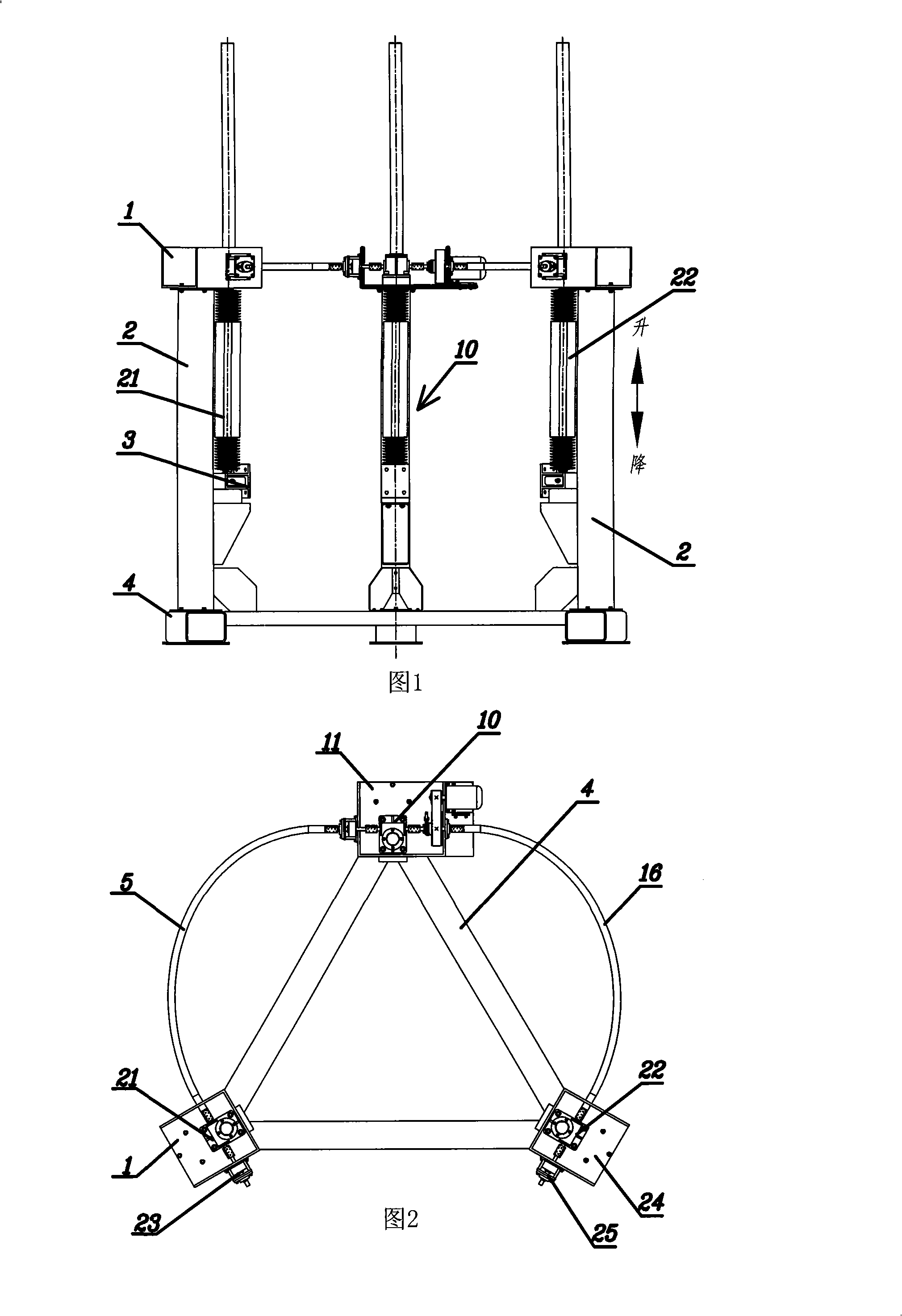
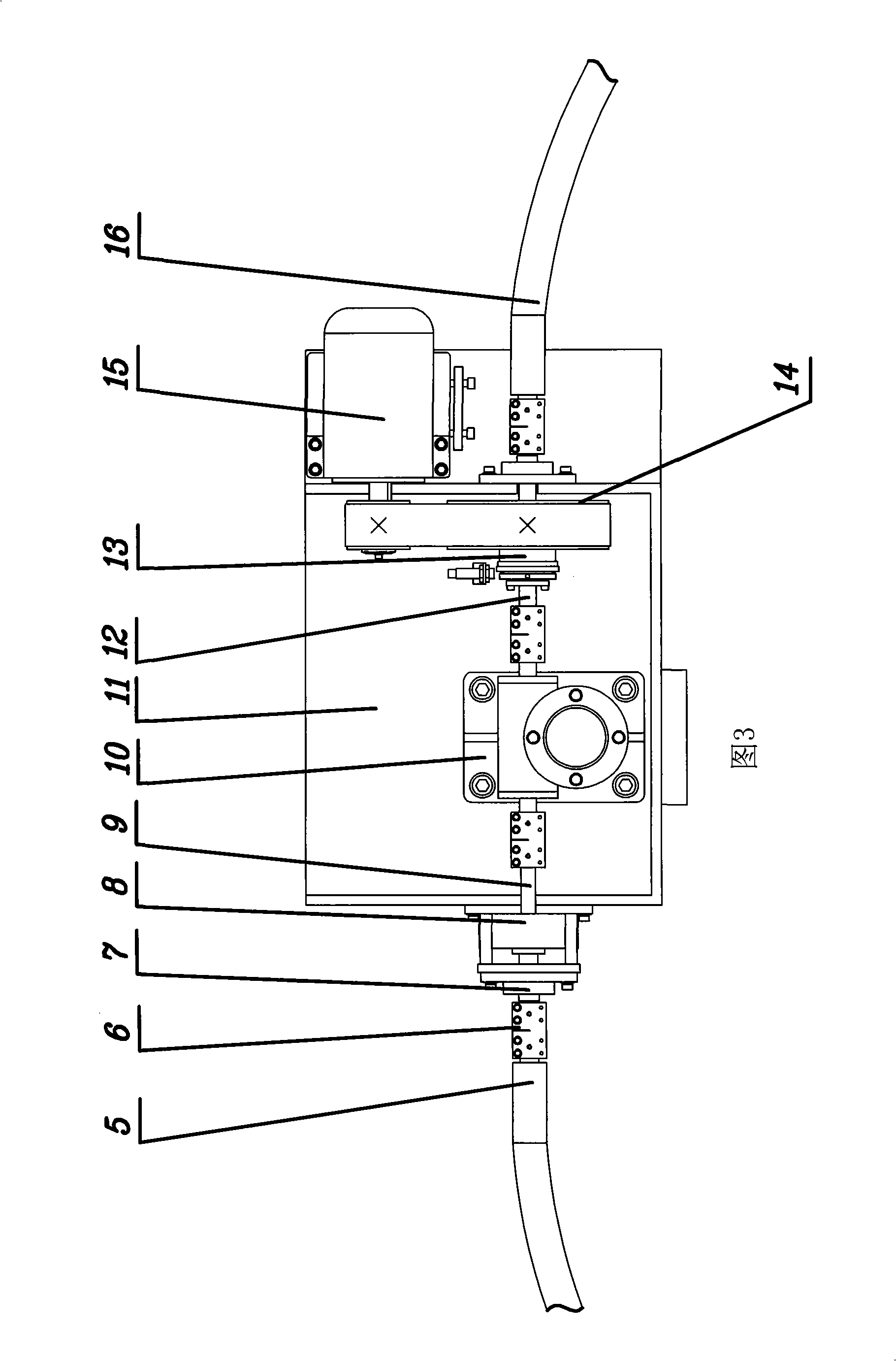
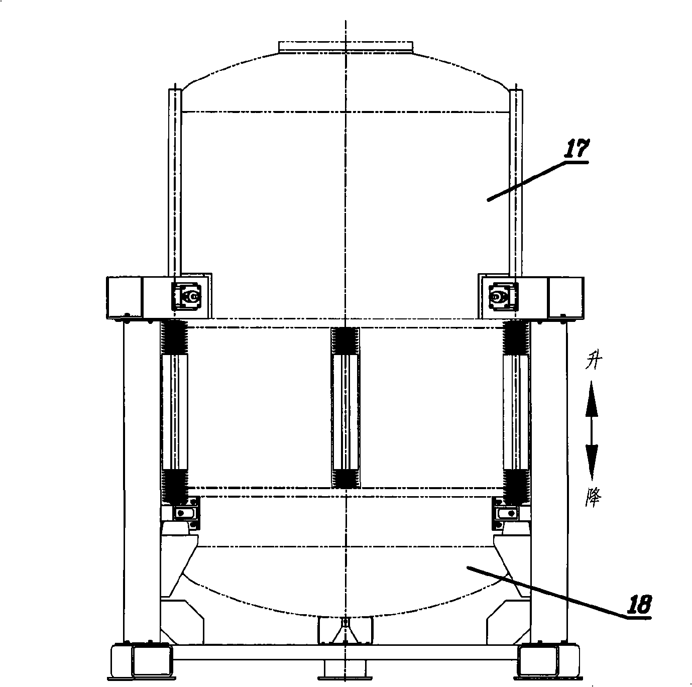
[0025] As shown in Fig. 1 to 5, the present invention has base 4 and screw lifter, and described base 4 is fixedly installed with three columns 2 and these three columns 2 form equilateral triangle distribution on a plane (that is, these three columns are positioned at three sides of equilateral triangle apex position), the upper ends of the three screw lifts are respectively fixedly installed on the fixing seats 1, 24, 11 on the top 2 of the corresponding column, wherein one end of the drive shaft of the first screw lift 21 is equipped with an A brake 23 and the other end is passed through the A brake 23. The first shaft coupling is connected with one end of the first flexible wire shaft 5, the drive shaft of the second screw lift 22 is equipped with a B brake at one end and the other end is connected with an end of the second flexible shaft 16 through the second coupling, and the second shaft coupling is connected with the second flexible shaft 16. One end of the drive shaft ...


PUM


Abstract

The invention relates to a multipoint synchronous lifting mechanism composed of a steel wire flexible shaft. Three upright columns distributed as equilateral triangle are arranged on a base of the multipoint synchronous mechanism; three screw lifter are respectively arranged on permanent seats of the corresponding upright columns tops; one end of a drive shaft of a first and a second screw lifter is provided with a brake and the other end is connected with one end of the corresponding steel wire flexible shaft by a coupling; one end of a drive shaft of third screw lifter is connected with one end of the brake shaft by the coupling and the other end of the brake shaft is connected with the other end of the same steel wire flexible shaft by the coupling; the other end of the drive shaft of the third screw lifter is connected with one end of a large synchronous belt wheel shaft, and the other end of the wheel shaft is connected with the other end of another steel wire flexible shaft by the coupling; the large synchronous belt wheel shaft is connected with a large synchronous pulley by a torque limiter and the large synchronous pulley is connected with a main shaft of a DC motor by a transmission pair. The multipoint synchronous lifting mechanism has the advantages of high synchronous precision, simple structure, low cost, high reliability, low noise, convenient speed regulation, simple installation and convenient matainance.

Description

technical field [0001] The invention relates to a synchronous lifting mechanism, in particular to a lifting mechanism that can be used for machines and equipment that require multi-point synchronous lifting. technical background [0002] The synchronous lifting mechanism is widely used in industrial equipment, such as various lifting platforms, the lifting movement when a certain part of the equipment needs to be opened, etc., especially in some occasions that require precise movement (synchronous error ≤ 1‰), the synchronous lifting mechanism The precision of movement often becomes the key to the operation of the equipment. To improve the accuracy of synchronous motion, the traditional method is to add precision guide devices and many detection methods to the previous synchronous mechanism (such as chain synchronous lifting mechanism, hydraulic synchronous lifting mechanism, etc.) to continuously correct the deviation generated during the movement. As a result, the system ...

Claims


Application Information

Patent Timeline
Patent Type & Authority Applications(China)
IPC IPC(8): B66F3/22B66F3/44
Inventor 王滋渊陈国红
Owner 48TH RES INST OF CHINA ELECTRONICS TECH GROUP CORP
Why Eureka
Try Eureka