Device for controlling helical lamp tube formation

A control device, a spiral technology, applied in glass molding, glass re-molding, manufacturing tools, etc., can solve problems such as rigid light refraction effect

Inactive Publication Date: 2008-09-17
丹尼尔·穆斯利
View PDF0 Cites 2 Cited by
  • Summary
  • Abstract
  • Description
  • Claims
  • Application Information

AI Technical Summary

Problems solved by technology

[0002] In the prior art, the shape of the existing spiral lamp tube B, such as Figure 16 As shown, the upper and lower tube diameters of the spiral lamp tube are the same, so the light refraction effect is rela

Method used


Image

  • Device for controlling helical lamp tube formation
  • Device for controlling helical lamp tube formation
  • Device for controlling helical lamp tube formation

Examples


Embodiment Construction

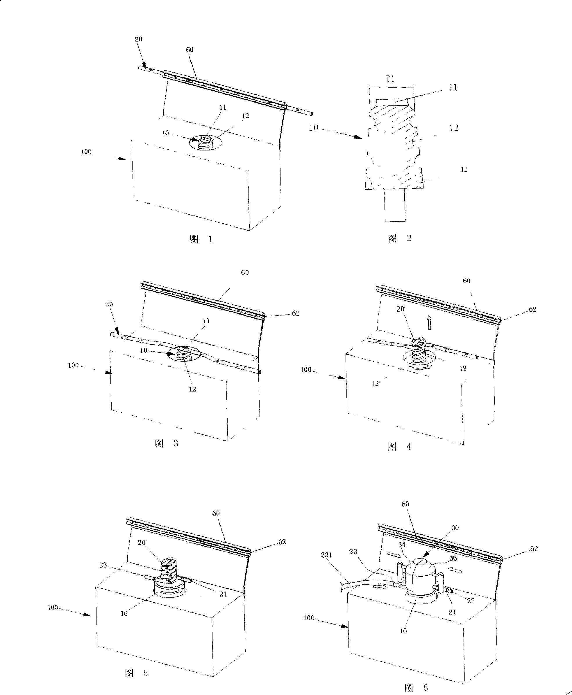
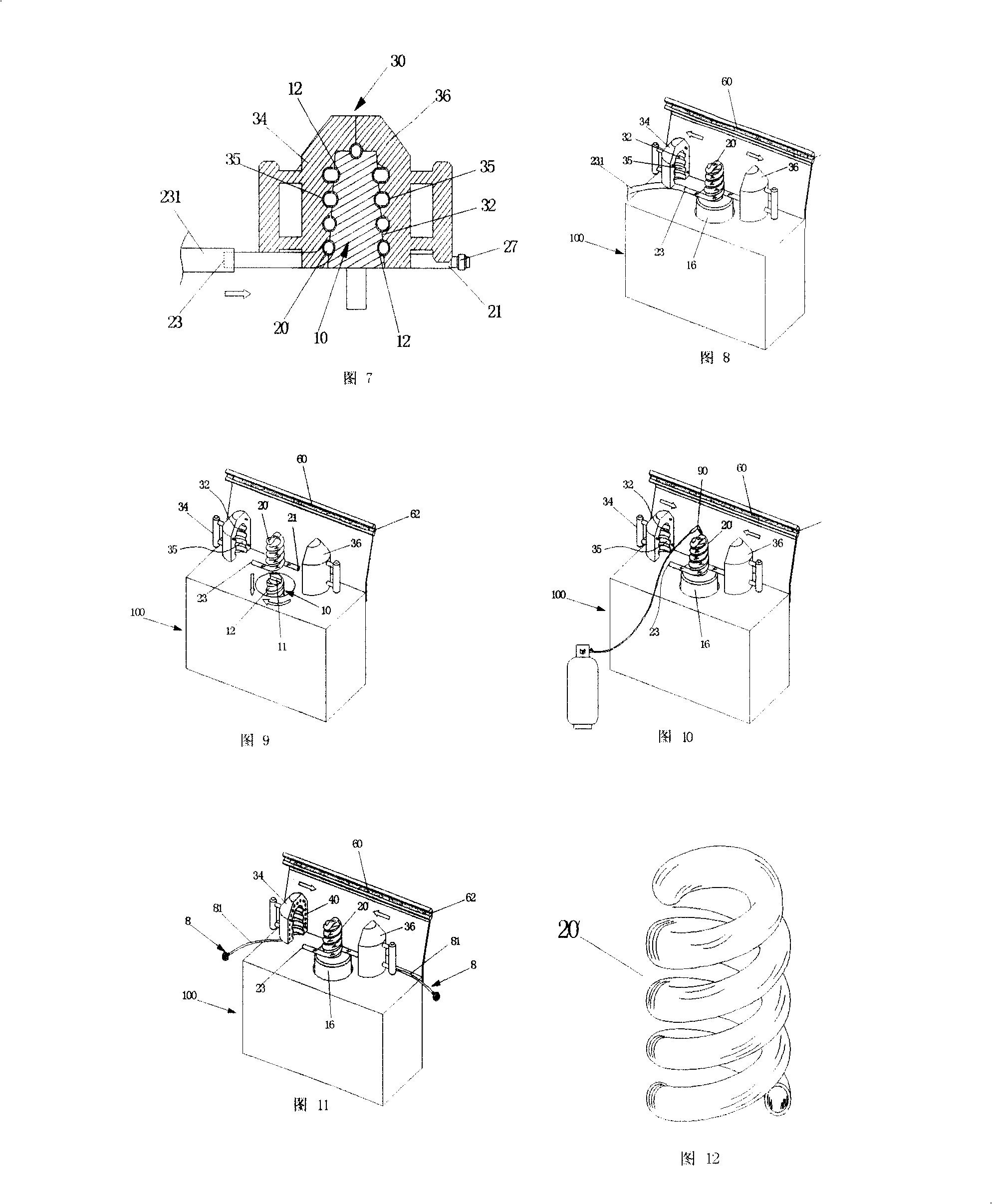
[0032] As shown in Figure 1, the heater 60 is installed above the side of the machine 100, so that the heater 60 is close to the inner mold 10, and its purpose is to operate on the inner mold 10 immediately when the operator takes out the glowing lamp tube 20. , to reduce the heat dissipation time of the lamp tube 20 and increase the plasticity time of the lamp tube 20; at this time, the inner mold 10 is located at the lower fixed point, as shown in Figure 3, after the plastic lamp tube 20 is taken out from the heater 60, its processing temperature is about 700 ° ~ 900°C, right, place the slightly central position of the lamp tube 20 on the transverse groove 11, and start the rotating device 16, as shown in Figure 4, make the inner mold 10 rotate forward and move upward, and the lamp tube 20 The lamp tubes 20 on the two sides of the center go around the spiral groove 12 until the inner mold 10 rises to the upper fixed point in the machine 100 (as shown in Figure 5), and the lam...


PUM


Abstract

The invention discloses a device for controlling spiral lamp forming process, which comprises a conical internal mold provided on the surface thereof with a spiral groove; a flexible lamp wound inside the groove of the internal mold to form a spiral lamp; and a left half-mold and a right half-mold that are respectively provided therein with an internal holding chamber and jointed on the surface of the spiral lamp to fix the shape of the spiral lamp. The diameters of the upper end and the lower end of the formed lamp are different, thus resulting in conical shape in longitudinal direction, so as to increase luminescence and transmission space and improve luminescence efficiency of the spiral lamp.

Description

technical field [0001] The present invention provides a control device for forming a spiral lamp tube, in particular a control device for forming spiral lamp tubes that are quick and easy to form and demould, and can form spiral lamp tubes with various appearance shapes. Background technique [0002] In the prior art, the shape of the existing spiral lamp tube B, such as Figure 16 As shown, the upper and lower tube diameters of the spiral lamp tube are the same, so the light refraction effect is relatively rigid. Therefore, how to make the upper and lower tube diameters of the spiral lamp tube different, so that the light refraction effect is full of changes, is the research of the present invention. topic. Contents of the invention [0003] The main purpose of the present invention is to provide a control device for forming a spiral lamp tube. Through a conical inner mold, a plastic lamp tube can be wound in the groove of the conical inner mold. The outer mold of the co...

Claims


Application Information

Patent Timeline
IPC IPC(8): C03B23/04C03B23/043
Inventor 丹尼尔・穆斯利
Owner 丹尼尔·穆斯利
Why Eureka
Try Eureka