
Projector

A projector and projection lens technology, applied in the field of projectors, can solve the problems of reducing the volume of the projector, reducing the volume of the light source, etc., and achieve the effect of reducing the volume, high color scale, and omitting the color wheel

Inactive Publication Date: 2008-09-17
BENQ CORP
View PDF0 Cites 2 Cited by
  • Summary
  • Abstract
  • Description
  • Claims
  • Application Information

AI Technical Summary

Problems solved by technology

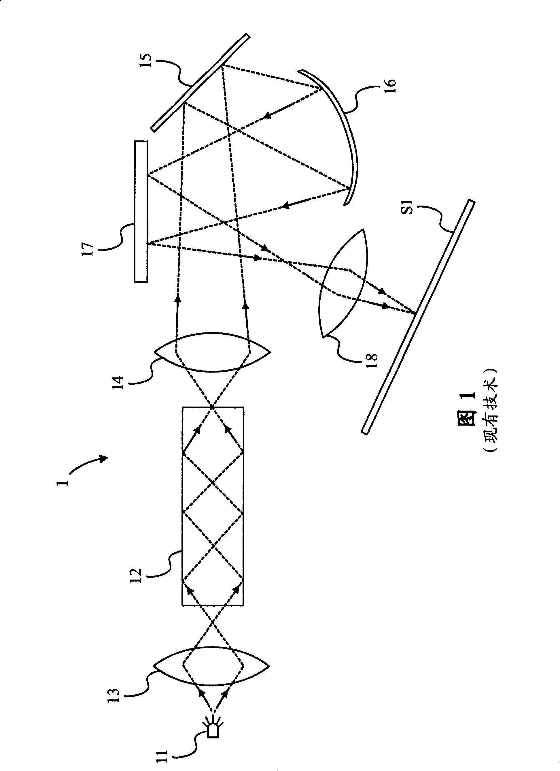
[0003] Although replacing the light source with a light emitting diode (Light emitting diode, LED) can greatly reduce the volume of the light source and further omit the use of a light wheel, the maintenance of brightness is still an important issue, and the light combining device and its subsequent lens and Devices such as mirrors still occupy a large volume, which limits the reduction in the volume of the projector

Method used


Image

  • Projector
  • Projector
  • Projector

Examples


Embodiment Construction

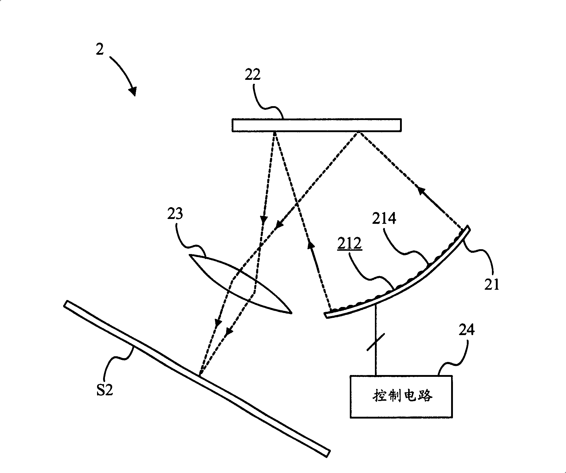
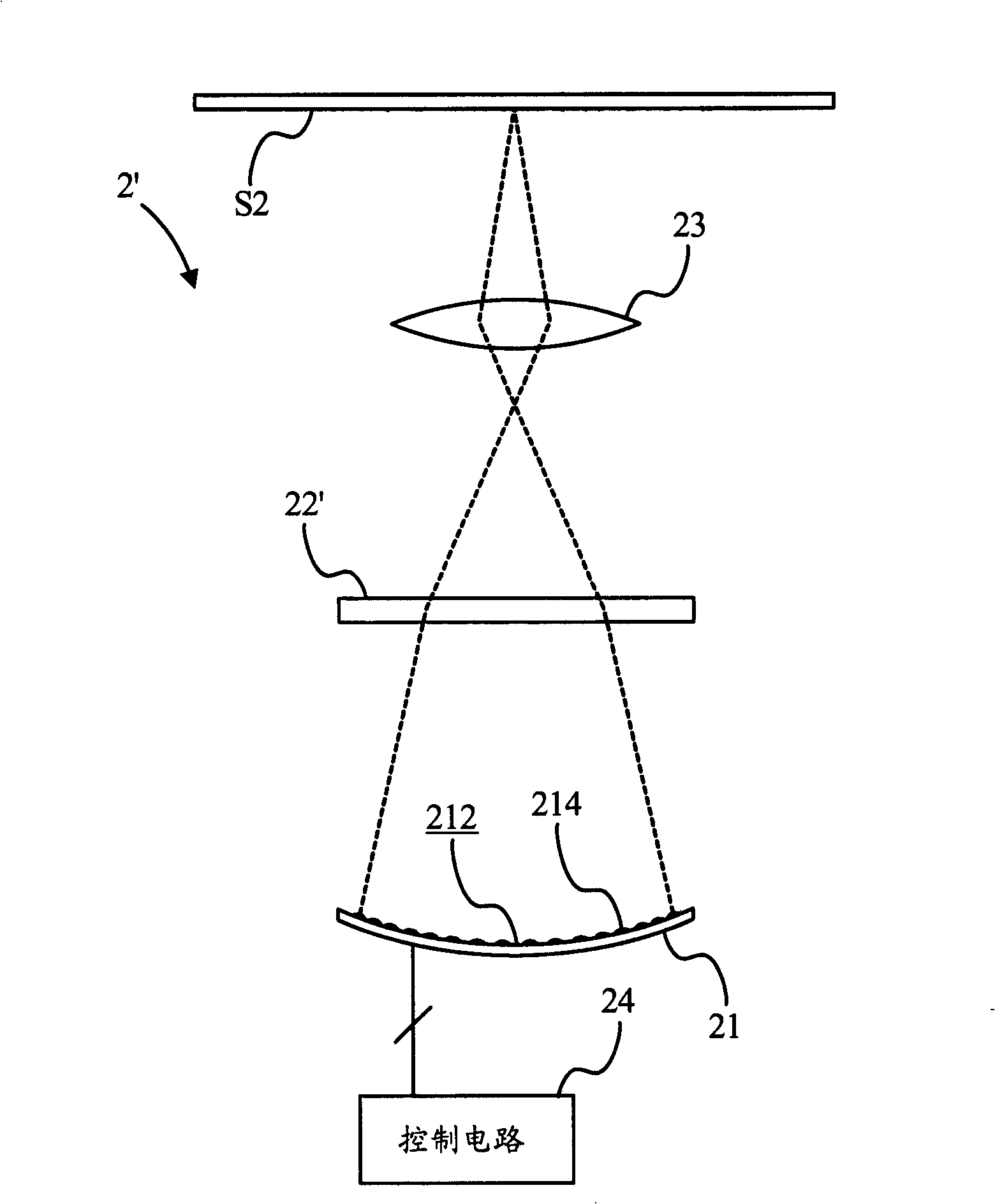
[0016] see figure 2 , figure 2 A schematic diagram of a projector 2 according to a first preferred embodiment is shown. The projector 2 of the present invention includes a curved light source device 21 , an image modulation device 22 and a projection lens 23 . The curved light source device 21 includes a curved surface 212 . A plurality of diode light emitting devices 214 are disposed on the curved surface 212 . The curved surface 212 is used to enable the diode light emitting devices 214 to generate a cohesive beam of light. The beam of light generally converges on a focal point of the projection lens 23 , which is determined by the radius of the curved surface 212 and the geometric configuration among the curved surface light source device 21 , the image modulation device 22 and the projection lens 23 . According to the first preferred embodiment, the radius of the curved surface 212 is 55 mm, the distance between the curved surface light source device 21 and the image m...


PUM


Abstract

The invention provides a projector, which includes a curved surface light source device, an image modulation device and a projection lens. The curved surface light source device is used to produce a bundle of light. The image modulation device is used to selectively modulate the bundle of light. The projection lens is used to project and image the bundle of light modulated by the image modulation device. Ulteriorly, the curved surface light source device contains a curved surface, on which a plurality of diode illuminating devices are provided. Each diode illuminating device contains a red light LED, a green light LED and a blue light LED. These LEDs of these diode illuminating devices controlled by the image modulation device in conjunction with a control circuit irradiate, the invention projecting camera is not needed to provide with a light combining device and a color block, thereby reducing volume and being able to maintain high brightness.

Description

technical field [0001] The present invention relates to a projector, and in particular to a projector with a curved light device. Background technique [0002] Since the light generated by the light source of the projector is modulated by an image modulation device and then projected into an image by a projection lens, the projector needs a light source with sufficient brightness to be uniformly mixed by a light combining device, and then the mixed light is modulated by the image modulation device. Finally, the modulated light is clearly projected and imaged on a screen by the projection lens. Please refer to FIG. 1 , which shows a schematic diagram of a conventional projector 1 . In most projector configurations, a condenser lens 13 is provided between the light source 11 and the light combining device 12 of the projector 1 to gather more light emitted by the light source 11 into the light combining device 12 . Moreover, the light mixed by the light combining device 12 pa...

Claims


Application Information

Patent Timeline
Patent Type & Authority Applications(China)
IPC IPC(8): G03B21/14G03B21/00H04N9/31
Inventor 鲍昭汉
Owner BENQ CORP
Learn More