
Method, device and system for sending and receiving communication system parameters

A communication system and parameter technology, which is applied in the system field of transmitting communication system parameters, can solve the problems of resource occupation, low efficiency of system parameters, cost, etc., and achieve the effect of improving utilization rate and transmission efficiency, improving transmission efficiency, and shortening time

Inactive Publication Date: 2008-09-17
HUAWEI TECH CO LTD
View PDF0 Cites 19 Cited by
  • Summary
  • Abstract
  • Description
  • Claims
  • Application Information

AI Technical Summary

Problems solved by technology

[0024] Using the negotiation method to transmit system parameters has the following disadvantages: because the negotiation process usually takes a long time, this method takes a long time to determine the parameters of the entire system; every time a parameter is changed, the negotiation process needs to be re-negotiated, which is very cumbersome. And it takes more time; in addition, because the system parameters need to be placed in the data block, it also takes up the resources of transmitting normal data
[0030] The frame header transmission method has the following disadvantages: because the system parameters are very important, in order to combat interference, it is necessary to perform more complex error correction coding on the frame header than the data block; in addition, the efficiency of using the frame header to transmit system parameters is relatively low
[0035] In wireless or power line communication, in order to complete this adaptive technology, it is necessary to transmit the changed system parameters in time. In the current method, either the sending and receiving parties need to negotiate, resulting in additional time overhead or additional frame header overhead. In addition, the blind estimation technique cannot be practically applied due to its limitations.

Method used


Image

  • Method, device and system for sending and receiving communication system parameters
  • Method, device and system for sending and receiving communication system parameters
  • Method, device and system for sending and receiving communication system parameters

Examples


Embodiment Construction

[0072] In order to make the purpose, technical solution and advantages of the present invention clearer, the following examples are given to further describe the present invention in detail.

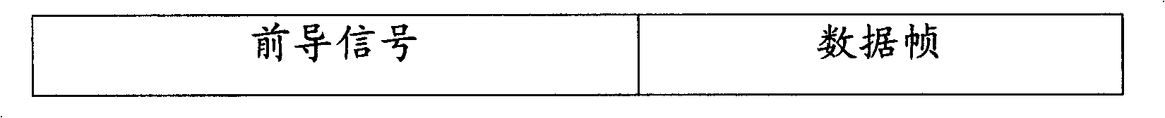
[0073] As mentioned above, the communication system usually sets a preamble signal before the data frame to assist the communication system to complete the synchronization process. Figure 7 A schematic diagram of the structure of the preamble signal and the data frame is given. Such as Figure 7 As shown, the preamble signal can be shared by several data frames, or can be used by each data frame. The preamble signal generally adopts an autocorrelation signal with better autocorrelation that can provide precise timing information. For example, the preamble signal can be a frame synchronization sequence, or a Barker code in radar, or other autocorrelation better signal, thereby providing precise timing information.

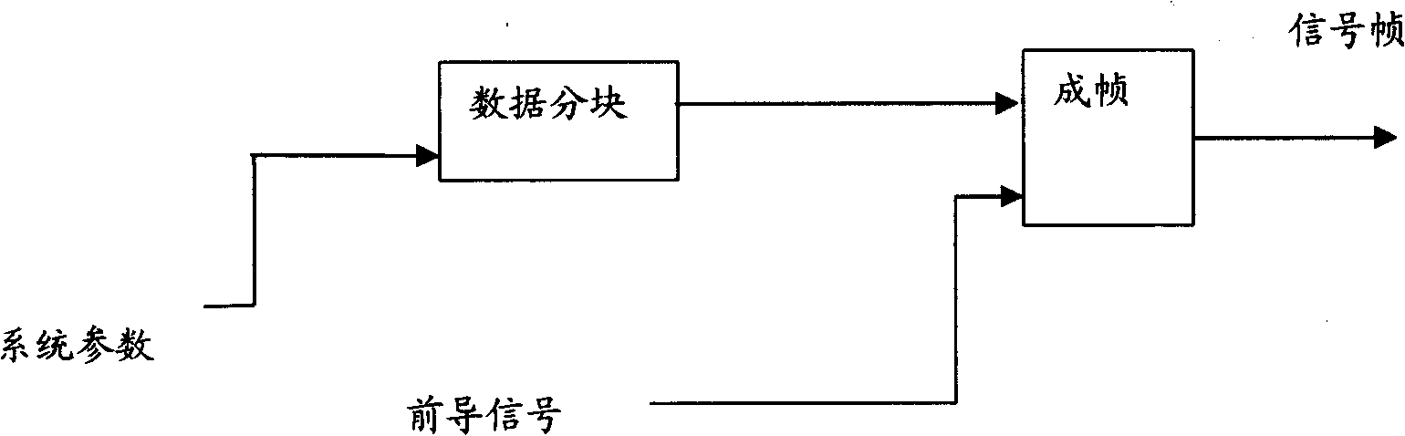
[0074] Figure 8 and Figure 9 A schematic diagram of the signal fr...


PUM


Abstract

The invention discloses a method for sending a communication system parameter, comprising the steps of: selecting an autocorrelation signal corresponding to the communication system parameter as a leading signal; combining the leading signal and a data frame to form a signal frame; sending the signal frame. The invention also discloses a method for receiving the communication system parameter, comprising: receiving the signal frame, identifying the autocorrelation signal as the leading signal in the signal frame; reading corresponding communication system parameter from a parameter table according to the autocorrelation signal. The invention also discloses a device sending the communication system parameter, a device receiving the communication system parameter, and a system transmitting the communication system parameter. The invention transmits the communication system parameter with the leading signal without occupying a data frame or a data frame header, so that the invention reduces cost of system, and enhances utilization ratio of channel as well as transmission efficiency.

Description

technical field [0001] The present invention relates to the technical field of transmitting communication system parameters, especially a method for sending communication system parameters, a method for receiving communication system parameters, a device for sending communication system parameters, a device for receiving communication system parameters, and a system for transmitting communication system parameters. Background technique [0002] A general model of a communication system is figure 1 As shown, it is mainly divided into a sending end, a receiving end, and a channel for transmitting signals between the sending end and the receiving end. [0003] exist figure 1 In the model shown, the sending end mainly includes a source and a converter. The role of the source is to convert all possible messages into the original signal. The converter converts the original signals such as speech and images that cannot be directly transmitted by electromagnetic waves into electr...

Claims


Application Information

Patent Timeline
IPC IPC(8): H04L27/26H04L1/00
Inventor 陈隽永
Owner HUAWEI TECH CO LTD
Features
  • Generate Ideas
  • Intellectual Property
  • Life Sciences
  • Materials
  • Tech Scout
  • Unparalleled Data Quality
  • Higher Quality Content
  • 60% Fewer Hallucinations
Learn More