
Constant current circuit and light emitting diode drive circuit

A technology of constant current circuit and constant current source, applied in the direction of electroluminescence light source, electric lamp circuit layout, circuit, etc., can solve the problem of variable range limitation, and achieve the effect of reducing power consumption, high versatility, and reducing chip area

Inactive Publication Date: 2008-09-17
RICOH MICROELECTRONICS CO LTD
View PDF1 Cites 11 Cited by
  • Summary
  • Abstract
  • Description
  • Claims
  • Application Information

AI Technical Summary

Problems solved by technology

[0021] However, the drain voltage of the NMOS transistor NT2 can only be adjusted from the voltage at which the NMOS transistor NT2 operates in the saturation region to the gate-source voltage range of the NMOS transistor NT2
That is, if the threshold voltage of the NMOS transistor NT2 is set as Vthn, and the excitation voltage is set as Vov2, the range of the voltage Vo of the output terminal OUT that can output a constant current without systematic errors is as follows: Vov2≤Vo≤Vthn+Vov2, there is The problem that the variable range of the voltage Vo of the output terminal OUT is greatly limited

Method used


Image

  • Constant current circuit and light emitting diode drive circuit
  • Constant current circuit and light emitting diode drive circuit
  • Constant current circuit and light emitting diode drive circuit

Examples


Embodiment Construction

[0083] Hereinafter, the present invention will be described in detail with reference to the embodiments shown in the drawings. In the following embodiments, although various limitations are made on constituent elements, types, combinations, shapes, relative arrangements, etc., these are merely examples, and the present invention is not limited thereto.

[0084] first embodiment

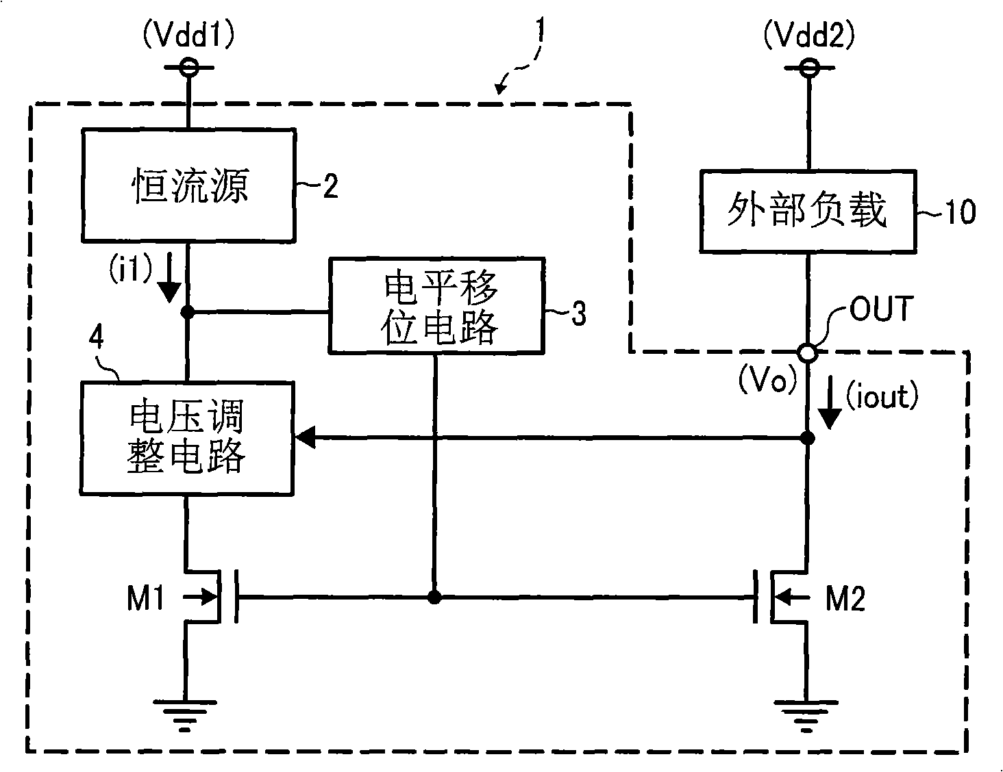
[0085] figure 1 It is a block diagram of a configuration example of a constant current circuit according to the first embodiment of the present invention.

[0086] figure 1 The constant current circuit 1 generates a predetermined constant current, which is supplied from the output terminal OUT to an external load 10 such as a light-emitting diode, and the NMOS transistors M1 and M2 generate a predetermined constant current i1 to output a constant current source 2, a level shift circuit 3 and The voltage adjustment circuit 4 is constituted. exist figure 1 In the case where the external load 10 ...


PUM


Abstract

The invention relates to a constant current circuit and light emitting diode drive device. The constant current circuit includes: a NMOS type transistor (M1) having current corresponding to a control signal inputted to a grid electrode; a NMOS type transistor (M2) for supplying current corresponding to the control signal inputted to the grid electrode; a voltage adjusting circuit (4) that controls a drain voltage of the NMOS type transistor (M1) according with the drain voltage of the NMOS type transistor (M2); a constant source (2) that supplies first constant current to the NMOS type transistor through the voltage adjustor (4), and a level shifter circuit (3) to shift a voltage at a connection node of the voltage adjustor and the constant current generation circuit, output a shifted voltage to each gate of the NMOS type (M1) and NMOS type (M2) transistors. The constant current circuit and light emitting diode drive device can be obtained with a simple circuit, and constant current with high precision not depending on output port voltage can be outputted, the output port voltage is outputted by no-reducing constant current output precision, and electric power consumption is reduced greatly.

Description

technical field [0001] The present invention relates to a constant current circuit, in particular to a constant current circuit for driving a light emitting diode (LED) and a light emitting diode driving device using the constant current circuit. Background technique [0002] Light-emitting diodes for display devices are generally driven with a constant current in order to reduce luminance variations. In the case of adjusting the brightness of the LED according to the application, it is adjusted by changing the current setting of the constant current circuit, but the voltage drop of the LED changes greatly due to the driving current. Therefore, the terminal voltage of the output transistor forming the output terminal of the constant current circuit largely changes. [0003] Usually, the constant current circuit uses the drain electrode of the MOS transistor as the output terminal. If the voltage of the output terminal changes greatly, the output current will change due to t...

Claims


Application Information

Patent Timeline
Patent Type & Authority Applications(China)
IPC IPC(8): H05B37/02G09G3/14H01L33/00H03F3/34
CPCH05B33/0812Y02B20/345H05B45/395Y02B20/30G05F1/56
Inventor 野田一平
Owner RICOH MICROELECTRONICS CO LTD
Features
  • Generate Ideas
  • Intellectual Property
  • Life Sciences
  • Materials
  • Tech Scout
  • Unparalleled Data Quality
  • Higher Quality Content
  • 60% Fewer Hallucinations
Learn More