
Multi-coordinate end milling process tool position optimization method using longitude line division tool bit

A tool position optimization, multi-coordinate technology, used in metal processing equipment, milling cutters, manufacturing tools, etc., can solve the problems of accurate calculation of line width and processing errors, loss of processing efficiency, etc., to control processing errors, improve processing efficiency, The effect of avoiding interference

Inactive Publication Date: 2008-09-24
BEIHANG UNIV
View PDF0 Cites 28 Cited by
  • Summary
  • Abstract
  • Description
  • Claims
  • Application Information

AI Technical Summary

Problems solved by technology

[0004] In the five-coordinate machining programming of the prior art, the research on how to maximize the machining efficiency of curved surfaces, accurately control machining errors, and avoid local and global interference in the machining process basically studies the above issues separately instead of They are studied as a whole. In this way, some methods need to manually adjust and control the attitude of the tool to effectively avoid interference, some methods cannot accurately calculate the line width and machining error, and some methods cannot achieve line-to-line. The overlap of the sequence is minimal, so that a serious loss of processing efficiency

Method used

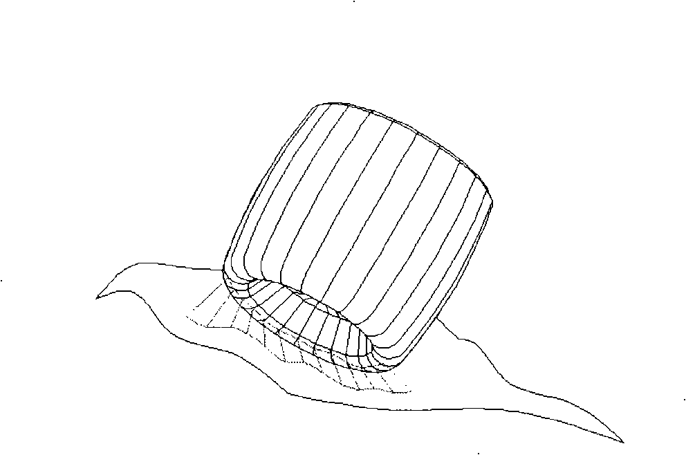
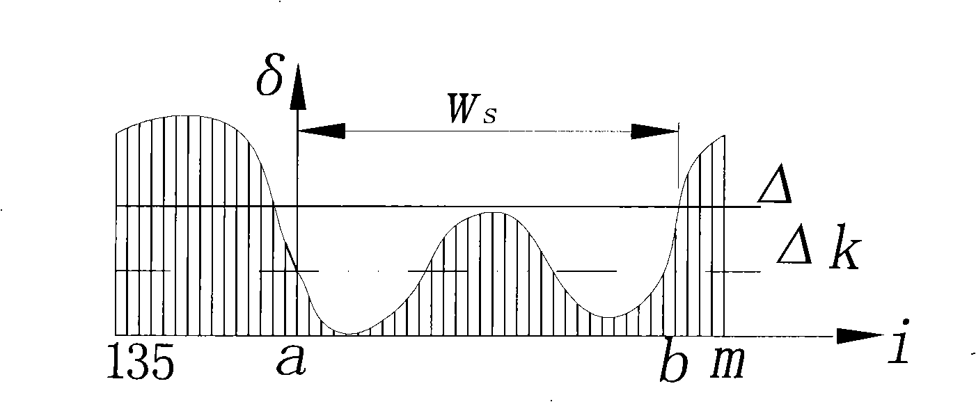
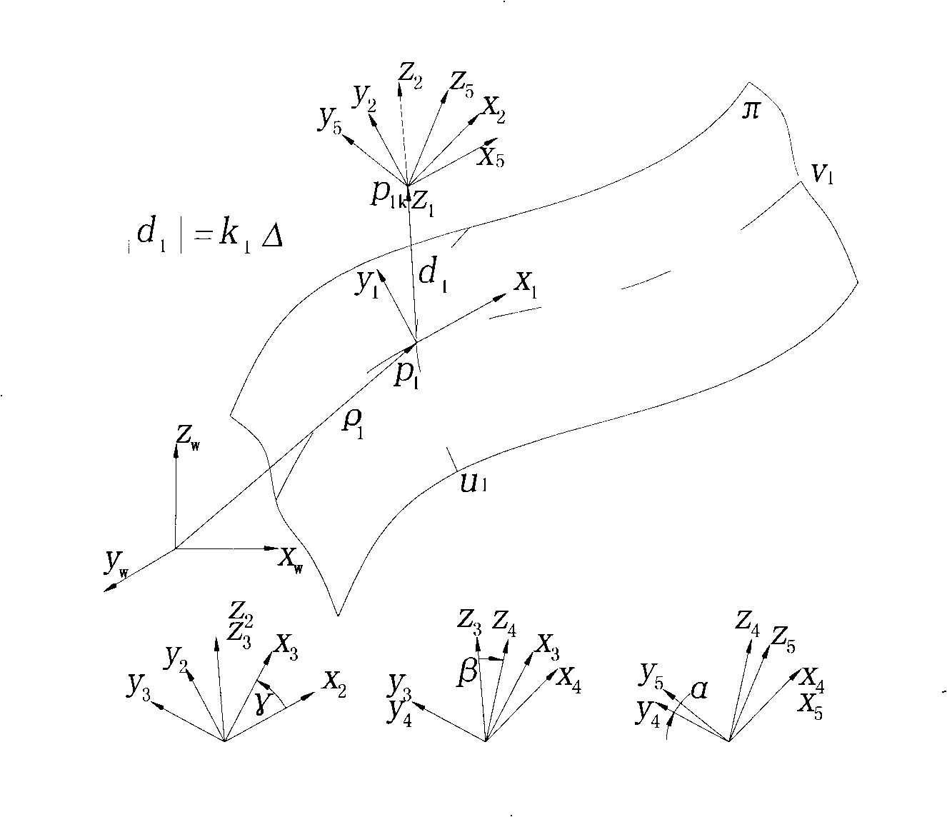

Image

  • Multi-coordinate end milling process tool position optimization method using longitude line division tool bit
  • Multi-coordinate end milling process tool position optimization method using longitude line division tool bit
  • Multi-coordinate end milling process tool position optimization method using longitude line division tool bit

Examples


Embodiment Construction

[0022] The preferred embodiment of the tool position optimization method for multi-coordinate end milling using a warp dividing tool according to the present invention includes the steps of:

[0023] First, the tool working surface can be discretized into a set of sufficiently dense meridians, and the shortest distance from each meridian to the workpiece design surface can be calculated to obtain a set of shortest distance line segments;

[0024] Then, the points on the shortest distance line segment located on the working surface of the tool can be connected to form a space curve, that is, the feature line, and the part of the feature line located within the programming tolerance zone can be regarded as an effective feature line segment, and all or part of the effective feature line segment can be selected As the effective feature line segment, the projection of the distance between the two ends of the effective feature line segment on a plane perpendicular to the tool feed di...


PUM


Abstract

The invention discloses an optimization method for a multi-coordinates end milling processing cutter spacing which adopts a meridian division cutter. Firstly, the working face of a cutter is dispersed into a set of enough dense meridians, and then the minimum distance among the meridians and a designed curved face so as to get a set of minimum-distance line segments; secondly, the points on the minimum-distance line segment at the cutter working face are connected together to form a curve in space, namely, a typical line; the typical line arranged in a programming tolerance range is regarded as an effective typical segment; with the distance between two endpoints of the effective typical segment, the surface projection vertical to the feed direction of the cutter is used as processing line width; the maximum of the processing line width is regarded as the object function of cutter spacing optimization; the non-negative distance between all meridians and the designed curved face is regarded as one of constraint conditions; a mathematic model of the cutter spacing optimization is constructed and is combined with a cutter rail for fair and smooth processing, getting the optimization cutter spacing through a solution procedure. The optimization method can be used for effectively avoiding interference and control the mismachining tolerance and improving the working efficiency.

Description

technical field [0001] The invention relates to a tool position and trajectory optimization technology in the machining process of a numerically controlled machine tool, in particular to a multi-coordinate end milling tool position optimization method using a warp line dividing tool. Background technique [0002] When machining a curved surface with a ball-end cutter, if the radius of curvature of the tool is equal to the radius of curvature of a point on the curved surface in a certain direction, and the concave and convex are opposite, a wide processing area can be processed on the curved surface at one time. The effective width of this area is called Actual line width or row width. Theoretically, the line width of surface processing should be measured by the length of the curve, but in general, the relative change of the normal vector of the processing area will not exceed 180 degrees, so it is simpler to use the chord length of the cross-section of the area . If the di...

Claims


Application Information

Patent Timeline
Patent Type & Authority Applications(China)
IPC IPC(8): B23C5/06B23C5/00
Inventor 陈志同张洪张俐
Owner BEIHANG UNIV
Learn More