Stress-relief blasting method

A technology of stress relief and blast holes, which is applied in blasting and other directions to ensure safety and progress of excavation, improve safety and eliminate hazards

A technology of stress relief and blast holes, which is applied in blasting and other directions to ensure safety and progress of excavation, improve safety and eliminate hazards

CN101270967AActive Publication Date: 2008-09-24POWERCHINA HUADONG ENG COPORATION LTD

Image

  • Stress-relief blasting method
  • Stress-relief blasting method

Examples


Embodiment Construction

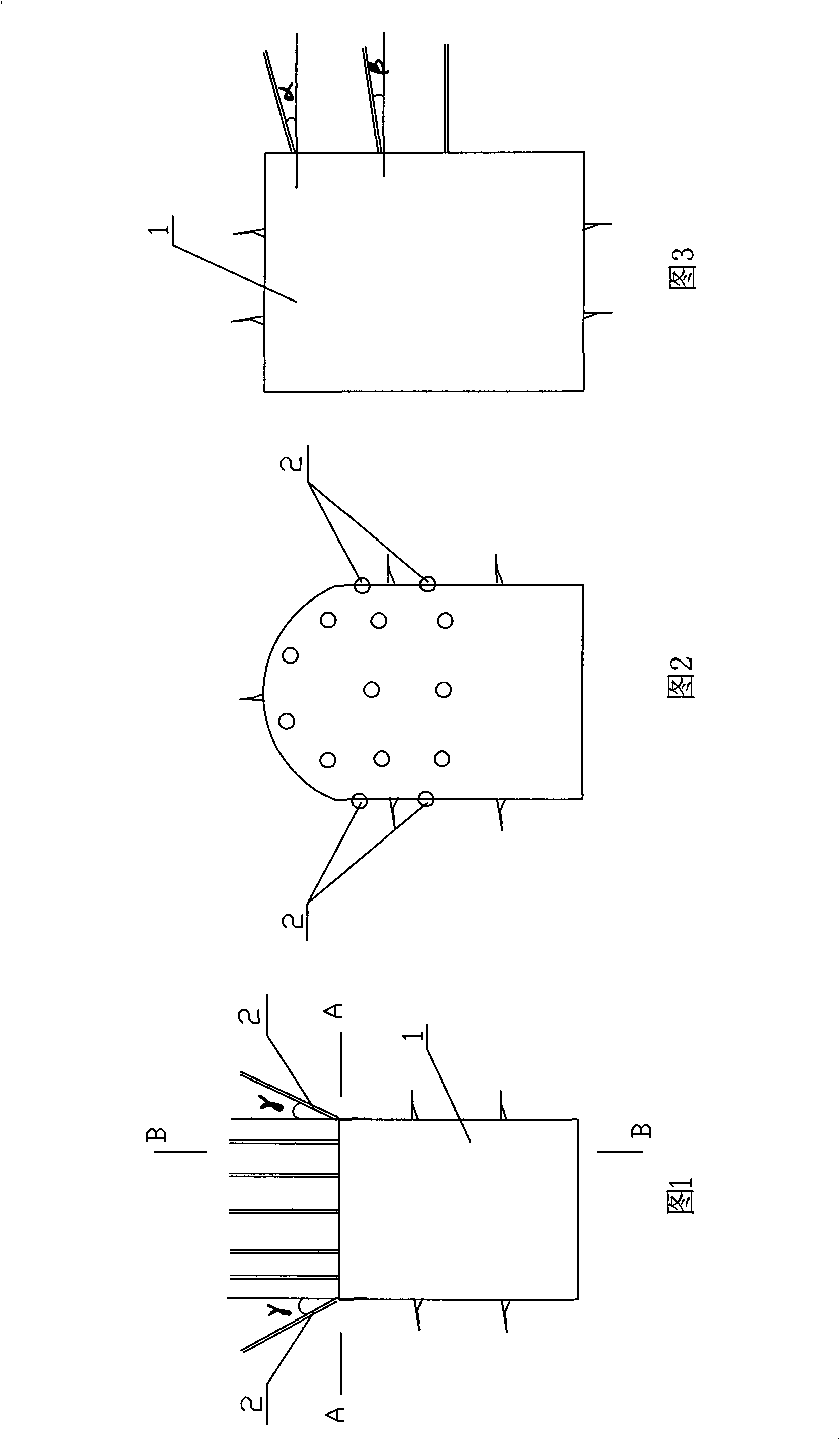
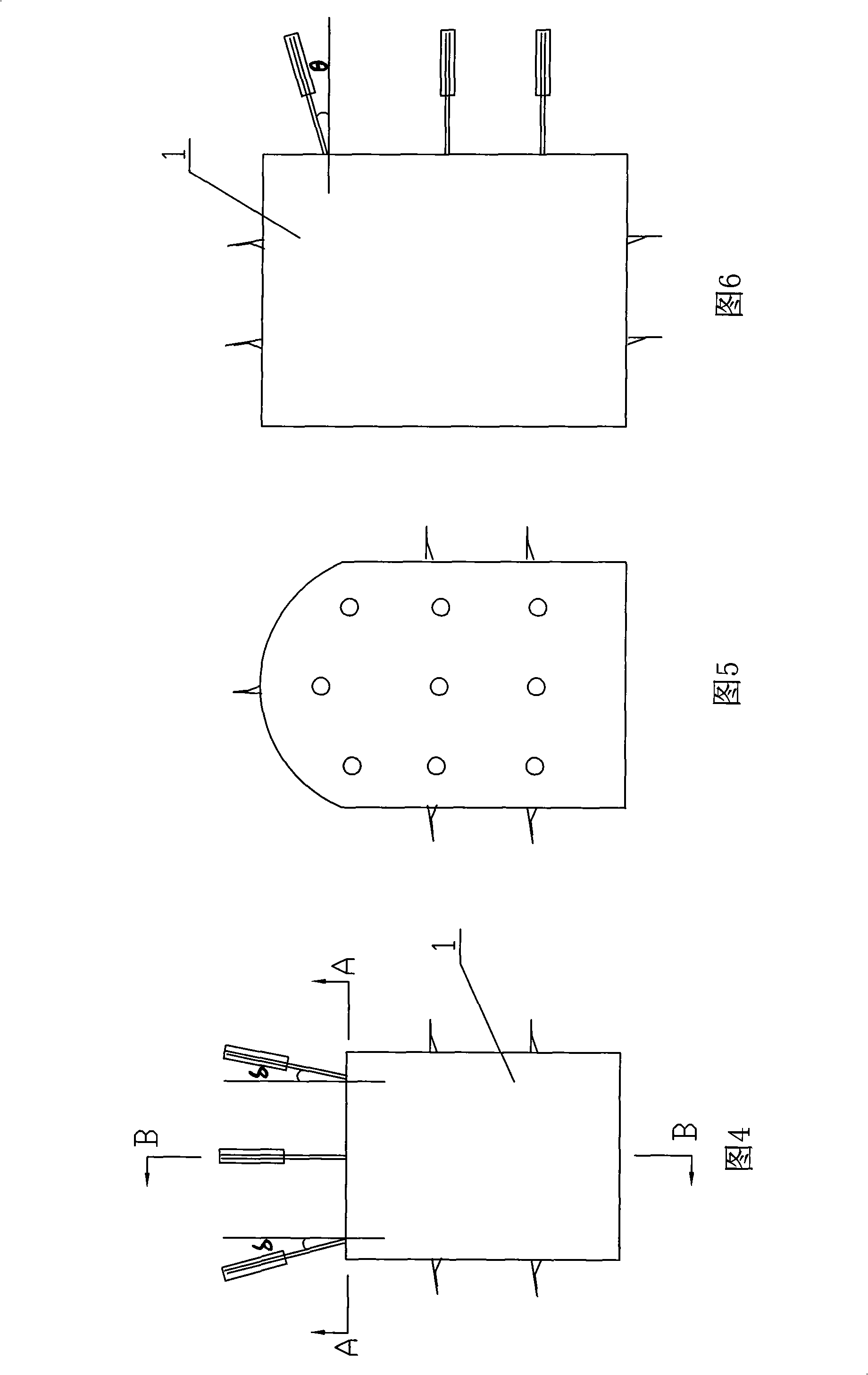
[0019] The steps of this embodiment include:

[0020] a. Drill a blast hole on the face of the tunnel, and its aperture is consistent with the diameter of the excavated blast hole;

[0021] b. Charge explosives in the blast hole;

[0022] c. Detonate after charging is completed;

[0023] For tunnel (tunnel, roadway) engineering, the above-mentioned stress-relieving blasting method can be incorporated into the normal blasting work procedure, but the stress-relieving blasting hole is given priority to blasting, and then the normal excavation blasting is carried out. The time delay between the two When there is no special requirement, the time delay between any two adjacent initiation sequences of on-site excavation blasting can be used. The blasting holes are generally arranged in the stress concentration area, and the principle of the hole depth is to reach or pass through the stress concentration area; at the same time, the number of blasting holes, the size of the hole and ...


PUM

PropertyMeasurementUnit
Hole lengthaaaaaaaaaa
Elevation angleaaaaaaaaaa

Abstract

The invention relates to a stress removal blasting method. The technical problems in the invention to be solved is to provide a stress removal blasting method which is suitable under the conditions of extremely strong rock burst and strong rock burst. The method can effectively reduce or eliminate the energy level of the stress concentration regions in rock body, to solve construction security problem caused by rock burst during tunneling deep-lying tunnel (tunnel, roadway) and ensure the tunneling progress. The stress removal blasting method includes the following steps: a. a blast hole is drilled on the tunnel face, and the aperture of the blast hole is consistent with the excavating blast hole; b. the blast hole is charged; c. the initiation is followed by charging. The invention can be applied in various projects, such as underground projects (such as water conservancy and hydropower project, traffics, mines, etc.) and excavation project (such as deep-lying tunnel).

Description

technical field [0001] The invention relates to a stress relief blasting method. It is mainly used in various water conservancy and hydropower projects, transportation, mining and other underground projects and excavation projects of deep tunnels. Background technique [0002] Rockburst is the destruction of surrounding rock caused by the sudden release of potential energy or strain energy accumulated in the rock mass during the excavation process of underground engineering, which can lead to casualties, damage to the working face or equipment, and its basic characteristics are sudden and violent. Strong rockbursts can cause large pieces of surrounding rock to burst and fall off, resulting in strong ejection, ejection of rock blocks and rock powder ejection; there is a bursting sound like blasting, and the sound is strong; it lasts for a long time and develops to the depth of the surrounding rock, and the damage range and The degree of block is large, and the impact depth i...

Claims


Application Information

Patent Timeline
24 Sep 2008
Publication
CN101270967A
IPC
F42D3/04
Inventors
单治钢; 朱焕春