Multi-shaft inertial sensor and method for measuring multi-shaft translation and rotation acceleration

A sensor, axis inertial technology, applied in the sensor field, can solve the problems of high complexity and cost, affecting the development of multi-axis sensor integration, and achieve the effects of large driving dynamic range, easy environmental noise and drift, and low inter-axis crosstalk sensitivity

Inactive Publication Date: 2008-09-24
江苏英特神斯科技有限公司
View PDF0 Cites 53 Cited by
  • Summary
  • Abstract
  • Description
  • Claims
  • Application Information

AI Technical Summary

Problems solved by technology

However, the extremely high complexity and cost of integrating multi-axis inertial sensors on a single chip has affected the development of multi-axis sensor integration.

Method used


Image

  • Multi-shaft inertial sensor and method for measuring multi-shaft translation and rotation acceleration
  • Multi-shaft inertial sensor and method for measuring multi-shaft translation and rotation acceleration
  • Multi-shaft inertial sensor and method for measuring multi-shaft translation and rotation acceleration

Examples


Embodiment 1

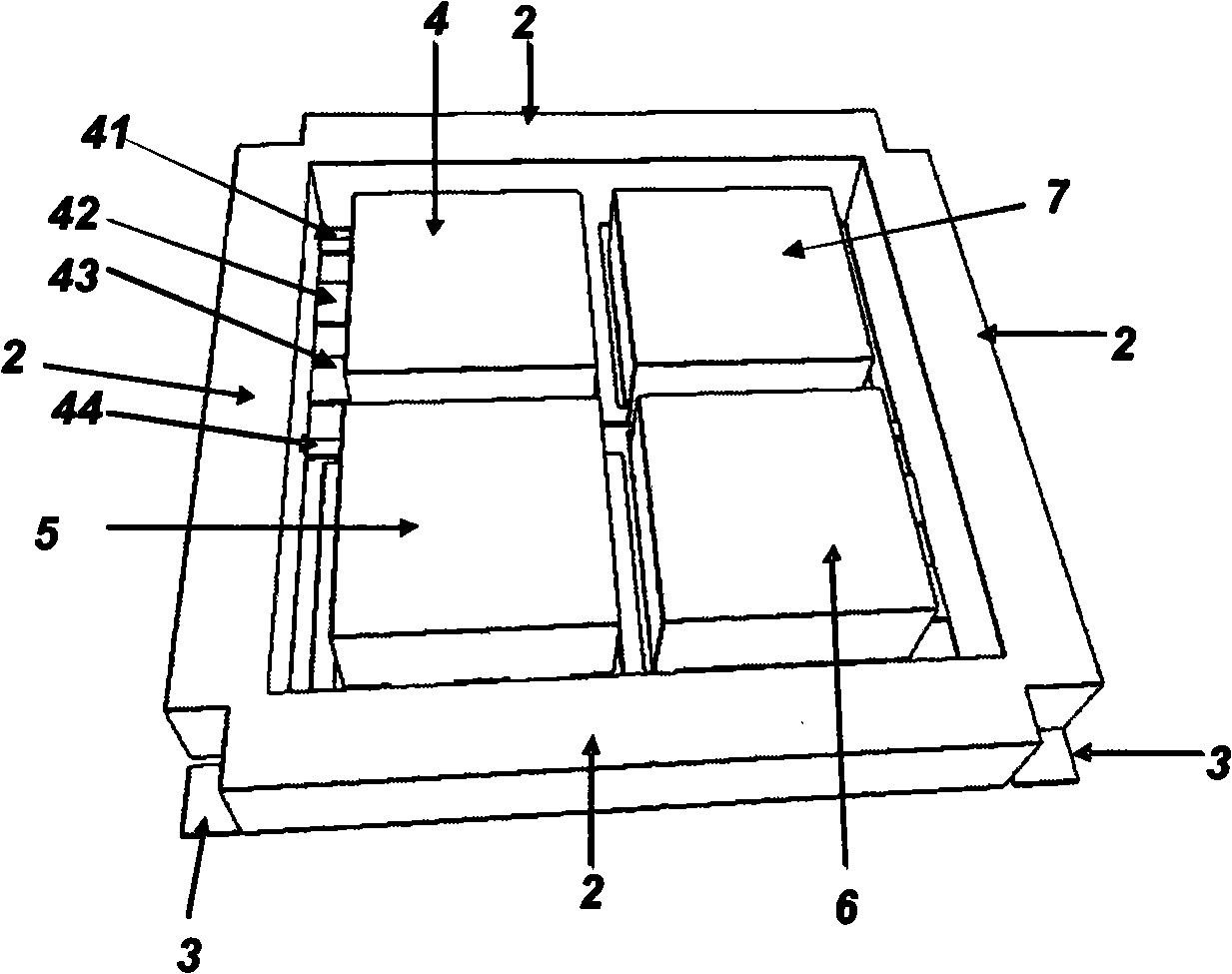
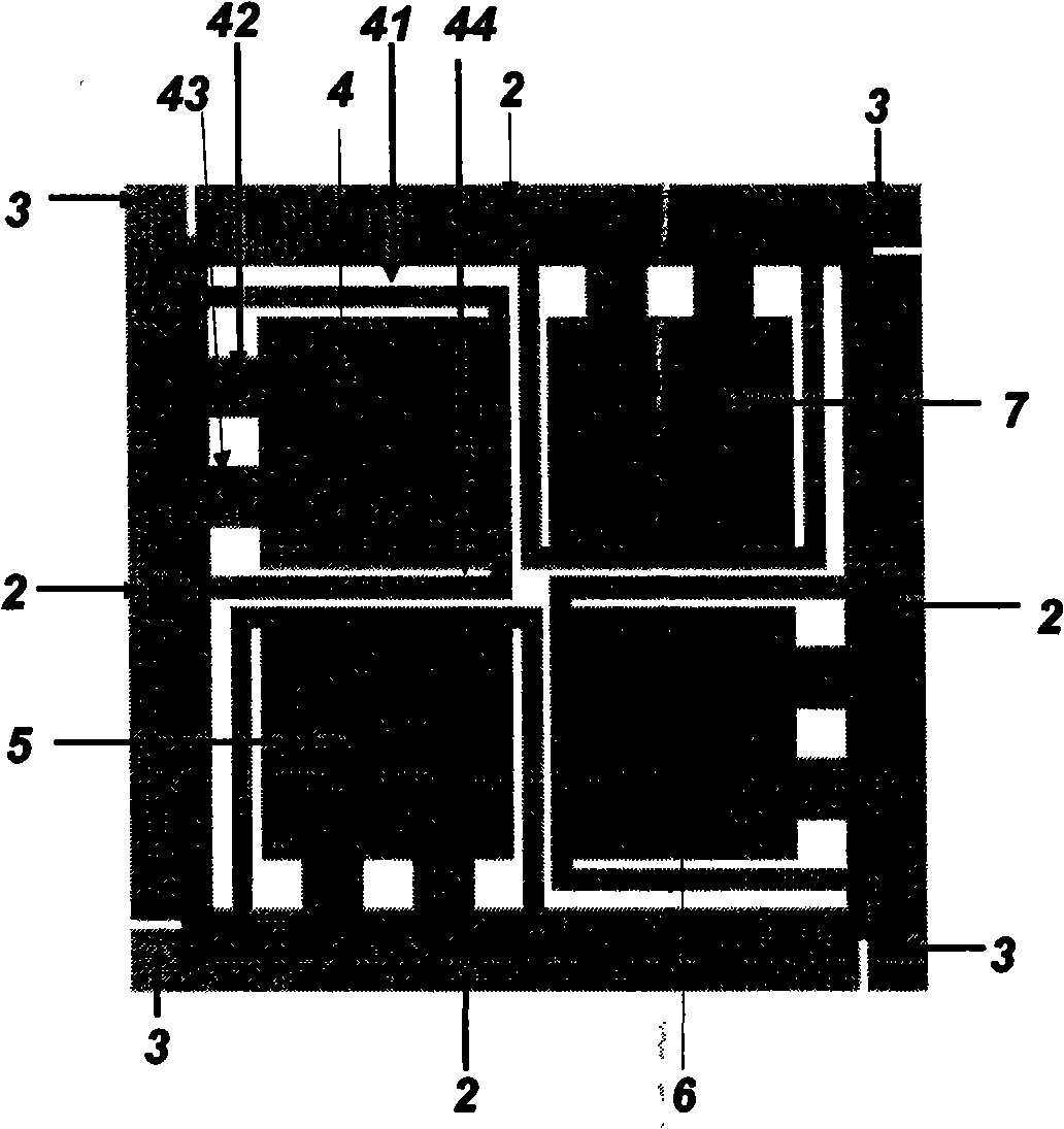
[0061] A first example consistent with the present invention is shown in figure 1 with figure 2 middle.

[0062] The structure of embodiment one has a square annular outer frame 2, and it will be subjected to figure 2 Driving in the paper direction (ie along the Z axis); four outer elastic beam arms 3 are placed on each outer corner of the frame 2 to play the role of suspending the frame. The four outer elastic beam arms 3 have the same height and extend outward from the bottom surface of the outer frame mass 2 . The inner ring structure of the frame 2 is four mass blocks (4-7), which occupy most of the area of ​​the inner ring of the frame 2. The centers of the four sensing masses occupy four symmetrical positions in frame 2. The four sensing masses in frame 2 have the same level and height. In the exposed structure 1, each sensing mass 4 has four parallel beam arms (41-44) connected to it, and two of the beam arms (41, 44) are connected to the frame and two remote be...

Embodiment 2

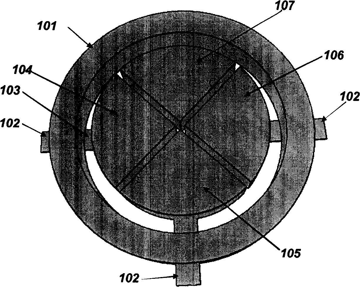
[0067] image 3 with Figure 4 A second example consistent with the present invention is given.

[0068] The structure in embodiment two has the outer frame 101 of circular ring, and it will be along the vertical plane on Figure 4 (ie, along the z-axis); four outer elastic beams 102 are used to support the frame 101 . The four outer beams 101 have the same height and extend outward from the bottom surface of the outer beam mass 101 . The four outer beam arms are evenly spaced along the frame. Figure 4 , they are along the X and Y directions. The inner structure of the frame 2 has four sense masses (104-107), which are in the frame 101, have different directions but the same sector shape. The frame 101 and the four inner masses (104-107) have the same height and thickness. The four masses (104-107) form two sensing pairs. The masses 105 and 107 form a pair. The masses 104 and 106 form another pair. In the structure disclosed in this embodiment, the proximal end of a ...

Embodiment 3

[0073] Figure 5 A detailed cross-sectional view of another capacitive motion sensor consistent with this invention is depicted. In this example the structural layer is sandwiched between two base layers forming a differential capacitance.

[0074] with the aforementioned Figure 1-4 Similar to the example in , the structural layer consists of a frame and a mass connected to it by elastic beam arms. In fact, removing the base layer on top, Figure 5 structure in and Figure 1-4 The structure in is very similar. After adding the top base layer and its electrodes, each mass in the structural layer constitutes the central plate in the differential capacitance structure. As the proof mass moves relative to the electrodes in the top and lower layers, one of the differential capacitances increases and the other decreases. The results are Figure 5 The example shown results in higher sensitivity and greater tolerance to temperature variations.


PUM


Abstract

The invention discloses a multi-axial inertial sensor and a method for measuring multi-axial translatory motion and rotating acceleration. The sensor includes a frame moving along a spindle, one or more pair of inductive mass blocks and an outer elastic structure. Each inductive mass block is hanged on the frame by an inner elastic structure, the symmetric axis of the inner elastic structure is consistent with the symmetric axis of the hanged inductive mass block, the frame is hanged on a sensor platform by the outer elastic structure; the inner elastic structure and the inductive mass block are installed to lead the centers of mass to deviate with each other along the direction of the spindle, and the outer elastic structure and the frame are also installed to lead the centers of mass to deviate with each other along the direction of the spindle. The multi-axial inertial sensor of the invention can measure a plurality of axial acceleration and rotation at the same time, which has high resolution, rather low inter-axle crosstalk sensitivity and strong resistance to environmental noise, and produces with low cost and mass.

Description

technical field [0001] The invention relates to the technical field of sensors, in particular to an inertial sensor and a method for simultaneously measuring multi-axis translational and rotational accelerations. Background technique [0002] Micro-accelerometers and gyroscopes have a wide range of applications in automotive control, game input and output, navigation and other fields. At present, the research and development of this kind of sensor mainly focuses on single-axis micro-gyroscope and multi-axis accelerometer. Of course, integrated multi-axis devices will find wide application in a variety of market segments by allowing a single chip to simultaneously measure acceleration and rotation. However, the extremely high complexity and cost of integrating multi-axis inertial sensors on a single chip has affected the development of multi-axis sensor integration. Therefore, a low-cost, single-chip, multi-axis inertial sensor has become a highly desired MEMS device. Con...

Claims


Application Information

Patent Timeline
Patent Type & Authority Applications(China)
IPC IPC(8): G01C19/56G01P15/02G01P15/125
Inventor 何野徐波
Owner 江苏英特神斯科技有限公司
Why Eureka
Try Eureka