Method and circuit for reducing switch concussion of switch type power supplier

A power supply, switching technology, used in instruments, electrical components, regulating electrical variables, etc.

Inactive Publication Date: 2008-09-24
RICHTEK TECH
View PDF1 Cites 4 Cited by
  • Summary
  • Abstract
  • Description
  • Claims
  • Application Information

AI Technical Summary

Problems solved by technology

[0007] However, this prior art approach has its disadvantages

Method used


Image

  • Method and circuit for reducing switch concussion of switch type power supplier
  • Method and circuit for reducing switch concussion of switch type power supplier
  • Method and circuit for reducing switch concussion of switch type power supplier

Examples


Embodiment Construction

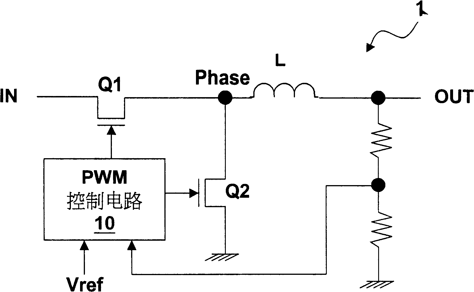
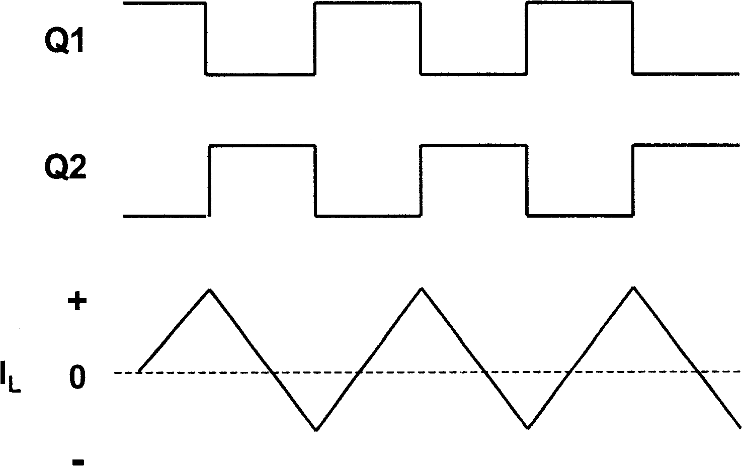
[0055] The main concept of the present invention is not to make the transistors Q1 and Q2 off at the same time; when the current I on the inductor L L When it is about to turn from positive to negative, the transistor Q2 is not completely turned off, but is placed in a "weak conduction" state, allowing low-flow current to pass through. so, with figure 2 Compared with the prior art practice shown, the present invention still has the high efficiency advantage of saving energy consumption, but with Figure 5 to Figure 7 Compared with the prior art shown, the present invention can greatly shorten the shaking time.

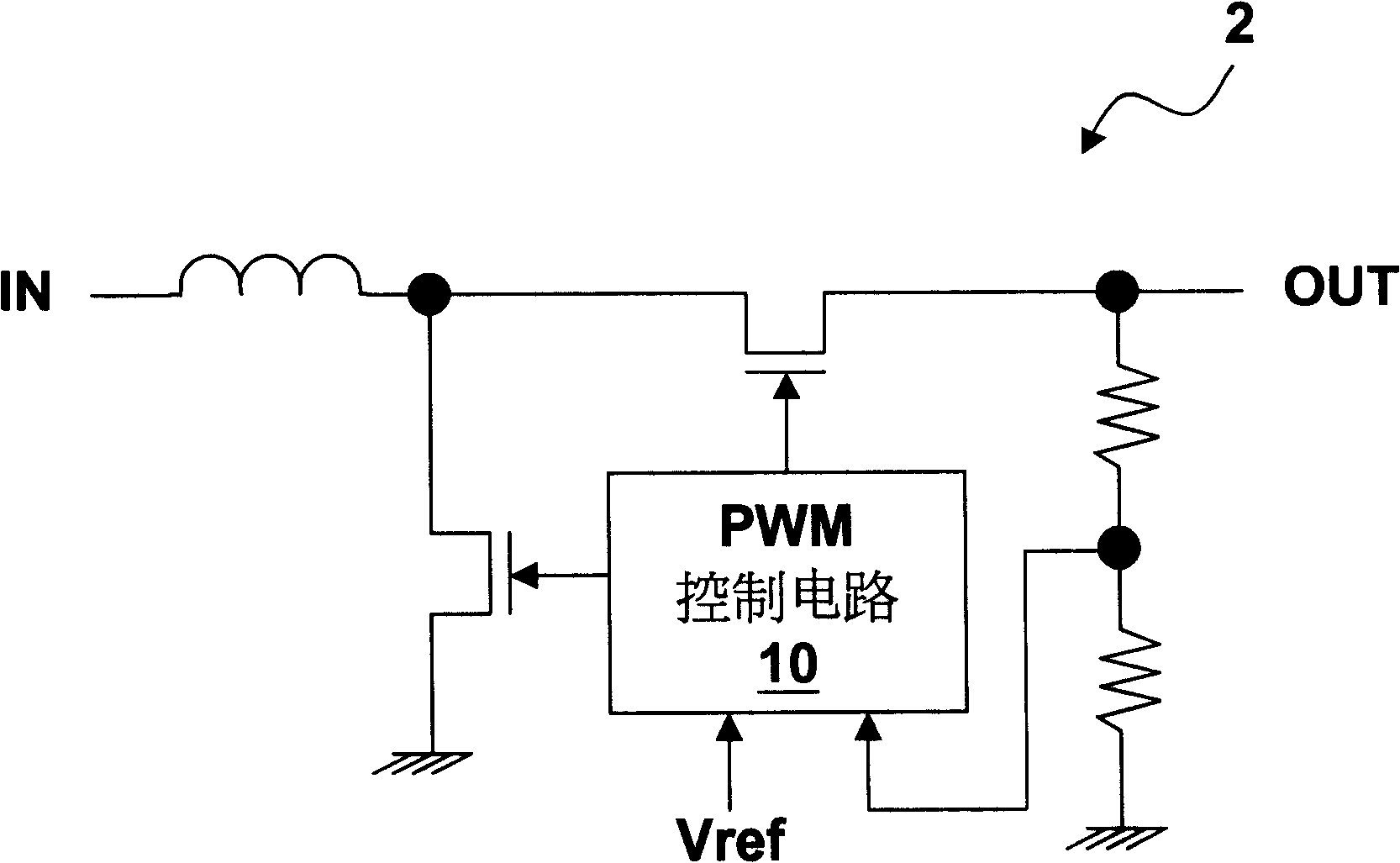
[0056] For the above concepts, please refer to Figure 8 , and compare Figure 5 and Figure 7 , should be easier to understand. In the prior art, the role of the transistor Q2 is only a switch, so there are only two states: fully open and fully closed. When the transistors Q1 and Q2 enter the aforementioned "sleep mode" in order to save energy consumption, the ...


PUM


Abstract

The invention provides a method and circuit to reduce the switching oscillation in a switching type power supply; the switching type power supply comprises two transistors and the two transistors can not enter an off state simultaneously. A phase locked loop can be further arranged in the invention so as to the output frequency of a pulse width modulation control circuit to be equal to a scheduled frequency. Compared with a synchronous switching type power supply, the power supply of the invention has the advantage of saving energy consumption, which can greatly shorten the oscillation period.

Description

technical field [0001] The present invention relates to a control method and circuit of a switching regulator, in particular to a method and circuit for reducing switching oscillation in a switching regulator. Background technique [0002] Commonly used switching power supplies include Buck, Booster and Inverter. First, let’s explain the step-down switching power supply. Its circuit structure is roughly as follows: figure 1 As shown, the step-down switching power supply 1 includes two transistor switches Q1, Q2, and the pulse width modulation control circuit 10 controls the on and off of the two transistors Q1, Q2, so as to control the current on the inductor L. The amount and direction of the current to deliver power to the output terminal OUT. The pulse width modulation control circuit 10 receives the feedback voltage extracted from the output terminal and compares it with a reference voltage Vref to determine how to control and switch the two transistors Q1 and Q2. [...

Claims


Application Information

Patent Timeline
IPC IPC(8): H02M3/155H02M3/156G05F1/56
Inventor 黄建荣曾国隆戴良彬
Owner RICHTEK TECH
Why Eureka
Try Eureka