Joint shaft and roller displacement unit therefor

A mobile unit, universal joint shaft technology, applied in the direction of coupling, elastic coupling, transportation and packaging, etc., can solve problems such as passenger injury, and achieve the effect of reducing sound, reducing sound and saving weight

Active Publication Date: 2008-09-24
轴造型工程公司
View PDF4 Cites 8 Cited by
  • Summary
  • Abstract
  • Description
  • Claims
  • Application Information

AI Technical Summary

Problems solved by technology

The sliding element of DE 198 31 016 C2 allows this only to a small extent, whereby there is a risk of injury to passengers due to bending out of the longitudinal axis

Method used


Image

  • Joint shaft and roller displacement unit therefor
  • Joint shaft and roller displacement unit therefor

Examples


Embodiment Construction

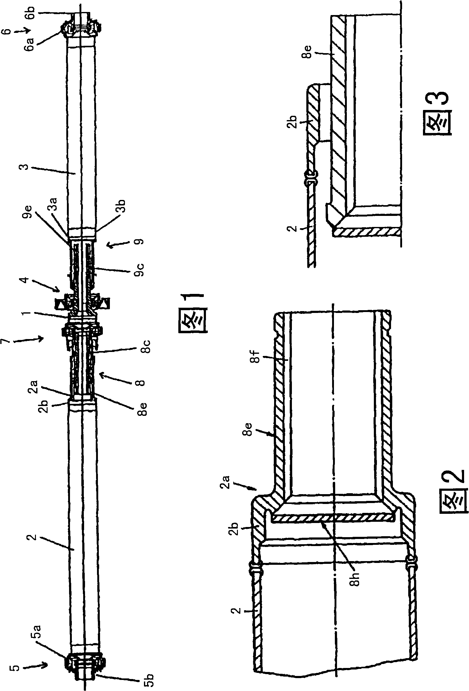
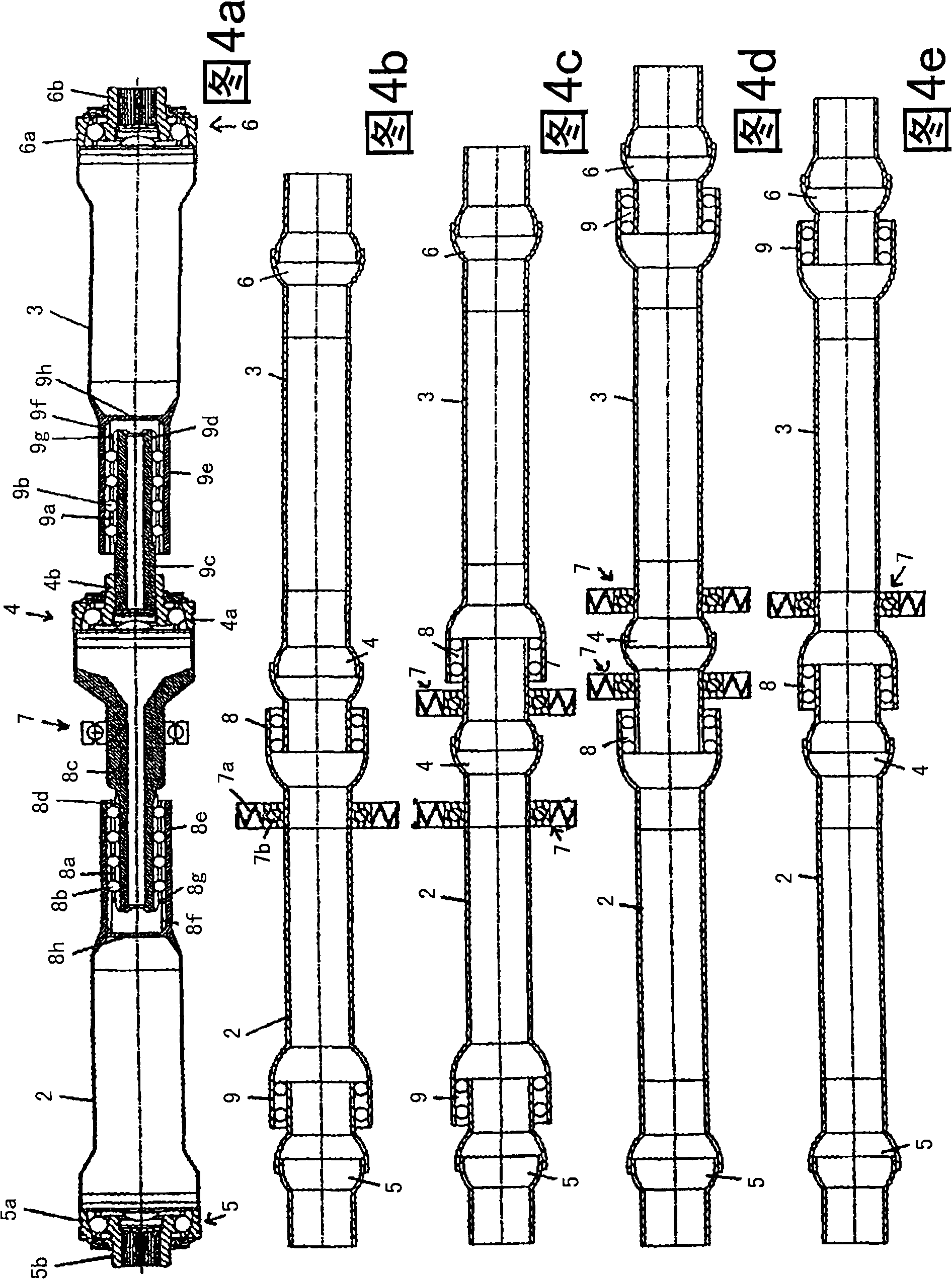
[0032] The cardan shaft 1 shown in FIG. 1 comprises a first shaft section 2 and a second shaft section 3 which are each designed as a hollow shaft tube. The two shaft sections 2 and 3 are connected to one another via an intermediate joint 4 which, in the embodiment shown, is designed as a counter-rail joint. The transmission-side end of the first shaft section 2 facing away from the central joint is connected to a transmission-side joint 5 . The differential-side end of the second shaft section 3 facing away from the center joint 4 is connected in the same manner to a differential-side joint 6 . Here too, the transmission-side universal joint 5 and the differential-side universal joint 6 are designed as counter-rail joints.

[0033] An intermediate bearing 7 with a shock absorber 7 a and a roller bearing 7 b is assigned to the intermediate joint 4 , which in the embodiment shown can be fastened to a vehicle floor assembly via a spring element. In addition, a first roller mov...


PUM


Abstract

The invention relates to a joint shaft comprising two shaft sections which are connected together in a rigid manner via a central shaft which is embodied as a constant velocity fixed joint. A constant velocity fixed joint is arranged on the end of each shaft section, which is oriented away from the central joint. At least one roller displacement unit, which enables both shaft sections to be displaced in an axial manner in relation to each other, is also provided.

Description

technical field [0001] The invention relates to a cardan shaft having two shaft sections which are connected to one another in a rotationally fixed manner via an intermediate joint designed as a constant velocity fixed joint, wherein in each shaft section respectively A constant-velocity fixed universal joint is provided on the end away from the intermediate universal joint, and two roller moving units are provided. In addition, the invention also relates to a roller displacement unit for such a cardan shaft. Background technique [0002] The cardan shaft is used, for example, as a longitudinal axis for connecting the front transmission output and the rear differential input of the motor vehicle. Such longitudinal axes are known, for example, from DE 102 08 325 C1 and DE 11 2004 000239 T5. Such cardan shafts use slip joints in order to enable axial movement between the shaft segments. The limited travel distance of such joints is disadvantageous in some applications. Fur...

Claims


Application Information

Patent Timeline
Patent Type & Authority Applications(China)
IPC IPC(8): B60K17/22F16D3/06
CPCF16D3/065
Inventor C·迪塞尔M·卢茨
Owner 轴造型工程公司
Why Eureka
Try Eureka