Shaping mold of members of mould shell

A formwork component and forming mold technology, applied in the direction of molds, mold separation devices, etc., can solve the problems of inconvenient demoulding, thin-walled tubes or thin-walled boxes, etc.

Inactive Publication Date: 2008-10-01
湖南邱则有专利战略策划有限公司
View PDF2 Cites 2 Cited by
  • Summary
  • Abstract
  • Description
  • Claims
  • Application Information

AI Technical Summary

Problems solved by technology

Such as the positive mold, as can be seen from their drawings, it includes a side mold surface and a lower mold surface (or a top mold surface), and the side mold surface and the lower mold surface...

Method used


Image

  • Shaping mold of members of mould shell
  • Shaping mold of members of mould shell
  • Shaping mold of members of mould shell

Examples


Embodiment Construction

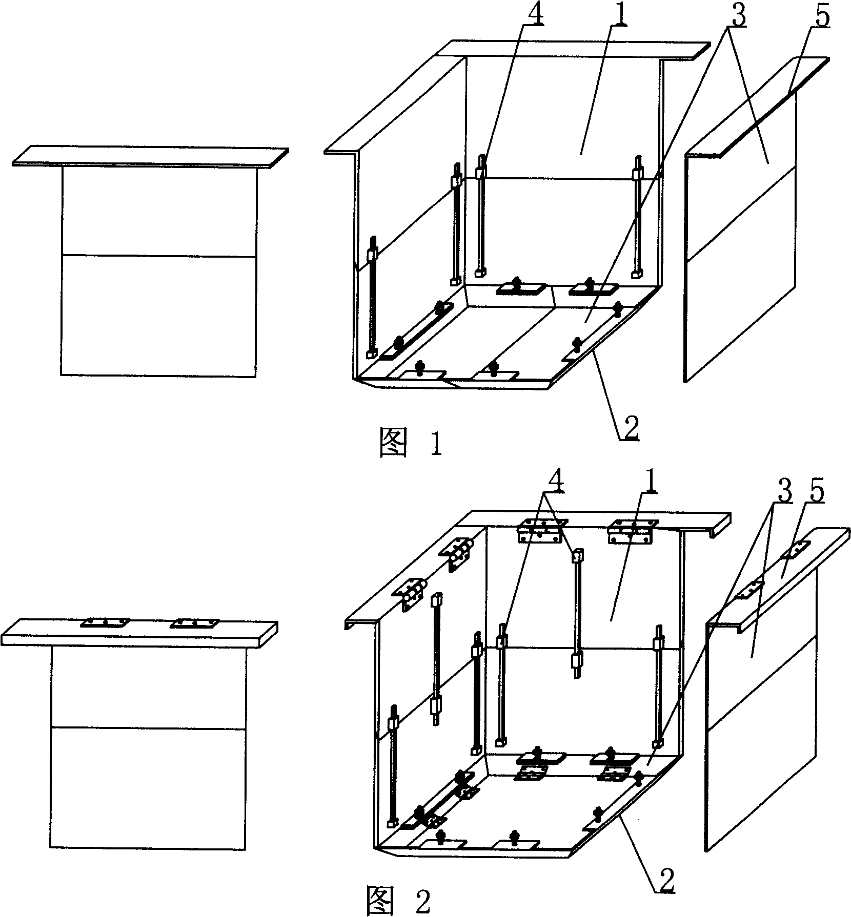
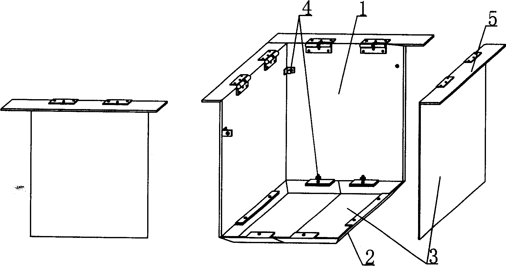
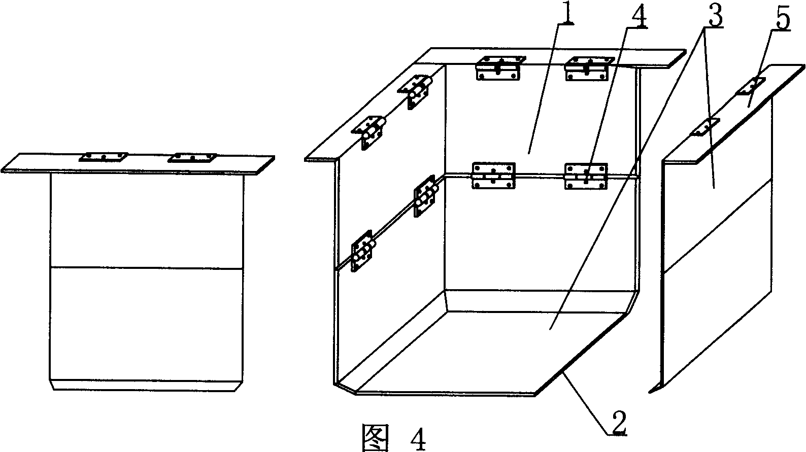
[0059] The present invention will be further described below in conjunction with the accompanying drawings and embodiments.

[0060] As shown in the accompanying drawings, the present invention includes a side mold surface 1 and a lower mold surface 2, and the side mold surface 1 and the lower mold surface 2 form a male mold, and is characterized in that the side mold surface 1 and the lower mold surface of the male mold 2 is composed of a template 3, the male mold is composed of at least two templates 3, and a splicing device 4 is arranged on the assembled template 3, and the template 3 of the side mold surface 1 of the male mold is connected with a hemming mold panel 5, and the side mold surface Four side formworks of 1 are hemming formwork panels 5. Fig. 1 is a schematic structural diagram of Embodiment 1 of the present invention. In each accompanying drawing, 1 is a side mold surface, 2 is a lower mold surface, 3 is a template, 4 is a splicing device, and 5 is a hemming m...


PUM


Abstract

The invention relates to a mold for molding a mold shell component. The mold comprises side mold faces (1) and a lower mold face (2); the side mold faces (1) and the lower mold face (2) form a male mold. The mold is characterized in that the side mold faces (1) and the lower mold face (2) of the male mold are made of molding boards (3) and the male mold is jogged and assembled by at least two molding boards (3), the jogged molding boards (3) are provided with a split unit (4), the molding board (3) of the side molding face (1) of the male mold is connected with a flanging mold face board (5) and the four side molding boards of the side mold face (1) are all flanging mold face boards (5). The mold is applicable to manufacturing thin pipes or thin boxes, in particular to manufacturing thin pipes or thin boxes with openings.

Description

[0001] This application is a divisional application of an invention patent application with the filing date of February 27, 2004, the application number of 200410005694.4, and the title of "a mold for molding shell components". (1) Technical field [0002] The invention relates to a mold for forming a mold shell component. (2) Background technology [0003] At present, cast-in-place reinforced concrete hollow slabs, especially the non-core-pulling hole-forming process of cast-in-situ reinforced concrete hollow slabs, are generally filled with thin-walled tubes or thin-walled boxes, which can meet the needs of various hollow slabs for evacuating concrete. The applicant applied for an invention patent with the application number 99115665.X and the title "fiber-reinforced thin-walled pipe (box) for reinforced concrete filling and its manufacturing method" on November 29, 1999, and the application number 99115666.8 , the invention patent titled "fiber-reinforced thin-walled box ...

Claims


Application Information

Patent Timeline
IPC IPC(8): B28B7/22B28B7/02B28B7/16B28B7/26
Inventor 邱则有
Owner 湖南邱则有专利战略策划有限公司
Why Eureka
Try Eureka