Removing device and removing method for polarizer

A polarizer and display panel technology, which is applied in chemical instruments and methods, optics, nonlinear optics, etc., can solve the problems of display panel fragmentation and poor removal efficiency, and achieve the effect of avoiding fragmentation

Inactive Publication Date: 2008-10-01
AU OPTRONICS CORP
View PDF0 Cites 7 Cited by
  • Summary
  • Abstract
  • Description
  • Claims
  • Application Information

AI Technical Summary

Problems solved by technology

The chemical formula polarizer removal method is mainly to immerse the display panel with the polarizer attached in the chemical solution of soluble colloid, so that the polarizer is peeled off from the display panel, but the chemical solution can only go from the edge of the polarizer to the edge of the display pan

Method used


Image

  • Removing device and removing method for polarizer
  • Removing device and removing method for polarizer
  • Removing device and removing method for polarizer

Examples


Embodiment Construction

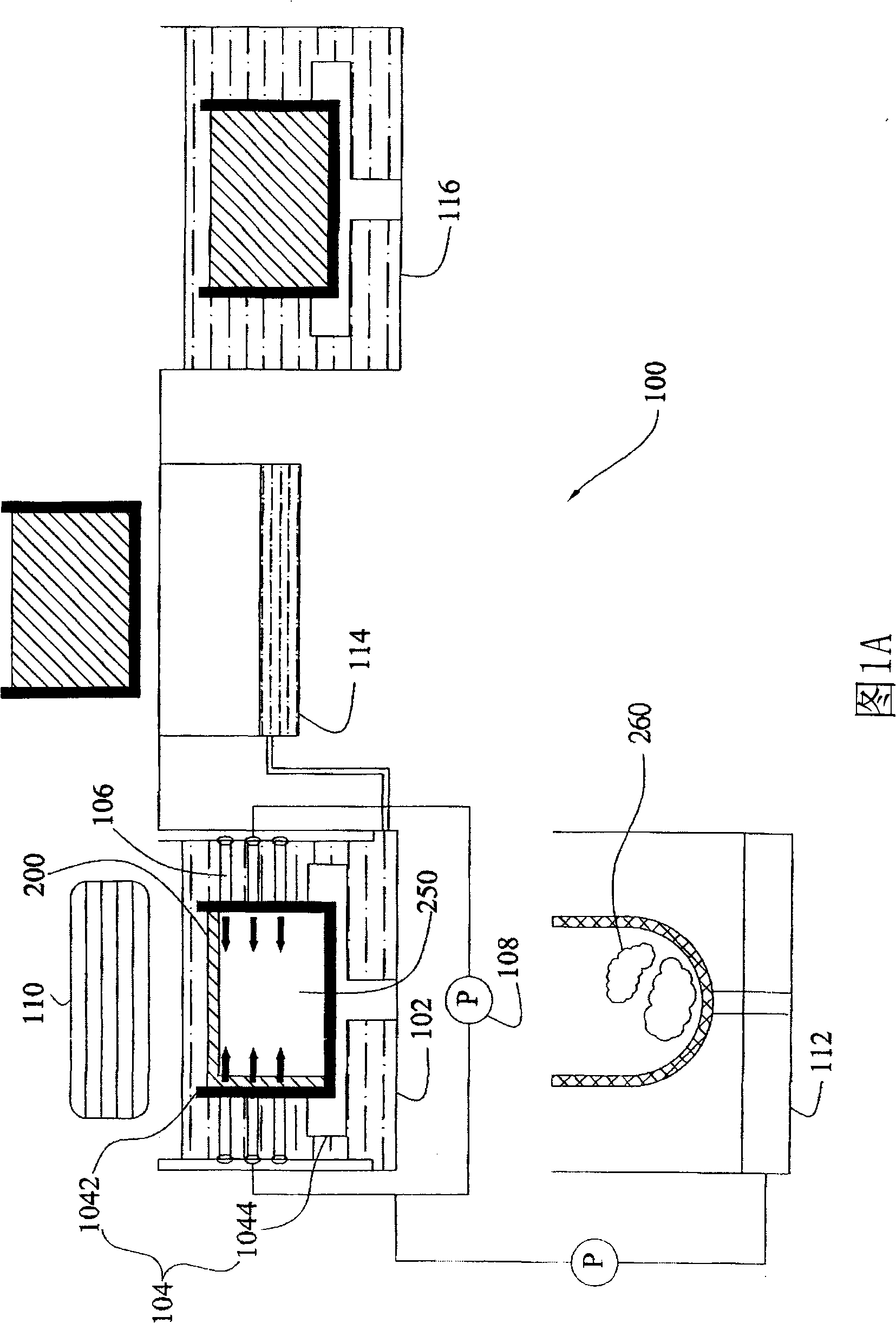
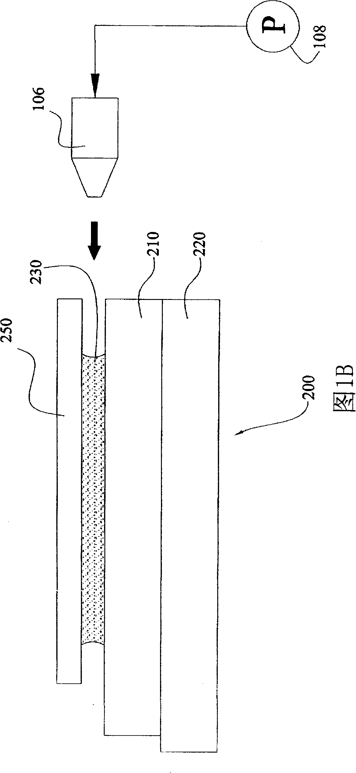
[0046] 1A and 1B below show an embodiment of the polarizer removing apparatus of the present invention. The polarizer removal device 100 is used to process the display panel 200 having the polarizer 250 on the surface, wherein the display panel 200 includes two glass substrates 210 and 220 , and the polarizer 250 is attached to the glass substrate 210 of the display panel 200 through a glue 230 . 230 is pressure sensitive adhesive (PSA, Pressure Sensitive Adhesive). Those skilled in the art know that any material of the substrate 200 or the colloid 230 can be used in the present invention, and the polarizer 250 can also be attached to the glass substrate 220 .

[0047] As shown in FIG. 1A , the polarizer removal device 100 includes a film removal tank 102 , a carrier unit 104 , an ejector 106 , a chemical solution supply unit 108 , a fan 110 , a waste collection tank 112 , a chemical solution collection tank 114 , and a cleaning tank 116 .

[0048] The film removing tank 102 i...


PUM


Abstract

The invention discloses a removal device for a polarizer and a method thereof, wherein, a surface to be processed is provided with at least one display panel of the polarizer. The polarizer is attached on at least one glass substrate of the display panel by a colloid. The removal device for the polarizer comprises a membrane removing groove which contains chemical solution, a bearing unit which is arranged in the membrane removing groove for bearing the display panel, and a plurality of ejectors which are arranged in the membrane removing groove for ejecting the chemical solution to the sides of the display panel. The removal device for the polarizer and the method of the invention can lead the polarizer on the display panel to be processed, which are particularly applied to the display panel with a thinned glass substrate, thereby effectively avoiding the fragment occurrence of the display panel.

Description

technical field [0001] The invention relates to a polarizer removing device and a method for treating a display panel with polarizers on the surface. Background technique [0002] The technology of liquid crystal display devices is mature and stable, and the price is popular. Consumers are gradually phasing out traditional picture tube display devices and favoring light and thin liquid crystal display devices. one of the products. [0003] The thickness of the glass substrate used in the display panel of the traditional liquid crystal display device is about 0.5-0.7mm, but in order to reduce the weight and thickness of the overall liquid crystal display device, it is gradually becoming a trend to use a thin glass substrate (thickness of about 0.05-0.4mm) . However, the use of thin glass substrates also leads to new process problems. For example, when the substrate becomes thinner, its mechanical strength is also weakened, which makes the substrate easy to break when it is ...

Claims


Application Information

Patent Timeline
IPC IPC(8): B32B38/10G02F1/1333
Inventor 张智顺
Owner AU OPTRONICS CORP
Why Eureka
Try Eureka