Flushing-free centrifugal type differential pressure sealing device for pump

A sealing device, centrifugal technology, applied in parts, pumps, pump components, etc. of pumping devices for elastic fluids, can solve the problems of short service life of seals, low running stability, high contact friction, etc. Achieve the effects of prolonging working life, reducing equipment maintenance and unplanned parking costs, reducing waste and environmental pollution

Inactive Publication Date: 2008-10-01
KUNMING UNIV OF SCI & TECH +1
View PDF0 Cites 5 Cited by
  • Summary
  • Abstract
  • Description
  • Claims
  • Application Information

AI Technical Summary

Problems solved by technology

These forms of parking seals rarely use elastic element devices, and mostly use medium pressure and fluid power to achieve sealing. The operation stability is not high, and some moving rings and static rings are not separated, so the structure is more complicated, the contact friction is more, and the service life of the seals shorter

Method used


Image

  • Flushing-free centrifugal type differential pressure sealing device for pump
  • Flushing-free centrifugal type differential pressure sealing device for pump

Examples


Embodiment 1

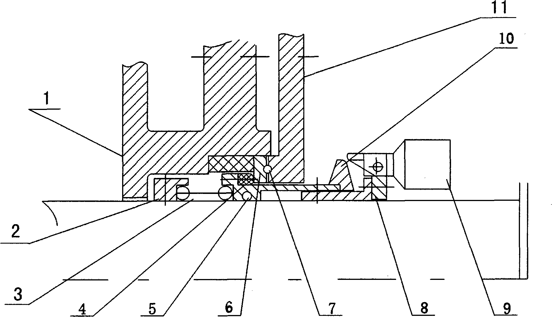
[0019] Such as figure 1 As shown, the stationary ring 6 is fixed in the assembly hole of the pump cover 1, the flying iron seat 8 is fixed on the pump shaft outside the pump cover 1, the rotating ring 4 is set on the flying iron seat 8, and the flying iron seat 8 is formed by the positioning pin. The sliding pair is connected, and the extended end of the rotating ring 4 is connected with a push ring 10 with a slope, and the other end surface of the rotating ring 4 is pressed against the stationary ring 6 when the pump stops. A pair of flying irons 9 are hinged on the flying iron seat 8 , and the force transmission end of the flying irons 9 touches and presses the slope of the push ring 10 . The elastic element 3 is located inside the gland 11. It can be a spring or a bellows. It is installed in the inner cavity of the pump cover together with the elastic element support 2. The elastic element support 2 is fixed on the pump shaft. One end of the elastic element 3 touches the el...

Embodiment 2

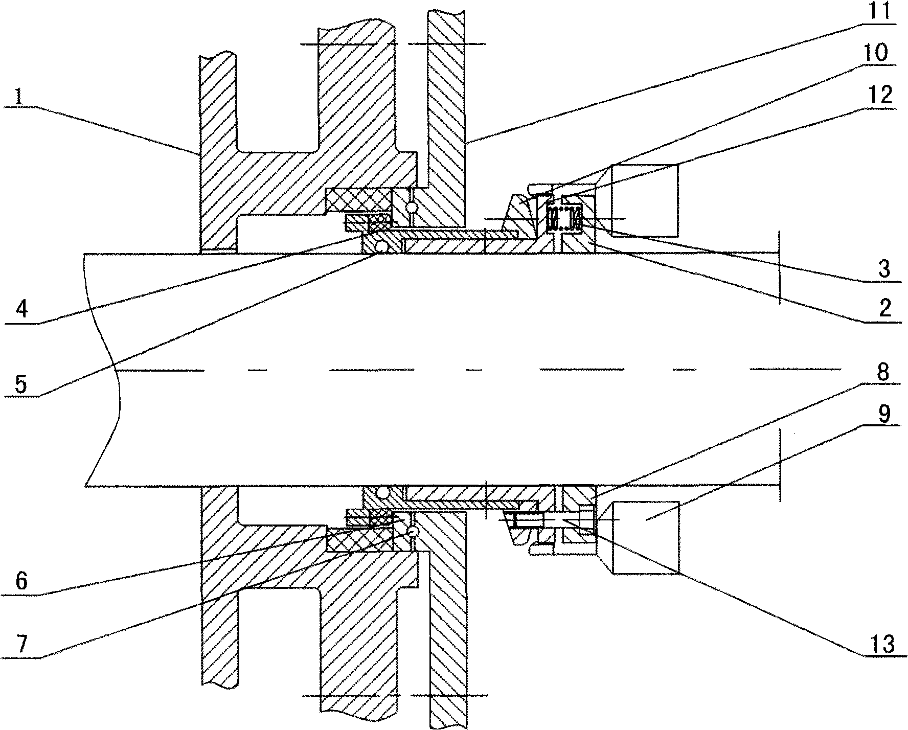
[0021] Such as figure 2 As shown, the stationary ring 6 is fixed in the assembly hole of the pump cover 1, the pressure ring 12 is fixed on the pump shaft outside the pump cover 1, the rotating ring 4 is set on the pressure ring 12, and the positioning pin and the pressure ring 12 form a slip Secondary connection, the extended end of the rotating ring 4 is connected with a push ring 10 with a slope, and the other end face of the rotating ring 4 is pressed against the stationary ring 6 when the pump stops. A pair of flying irons 9 are hinged to the flying iron seat 8 and then fixed on the pump shaft, and the force transmission end of the flying irons 7 touches and presses the slope of the push ring 10 . The elastic element 3 is located outside the gland 13, and can be a spring or a bellows, one end of which is pressed on the pressure ring 12 fixed on the pump shaft, and the other end is pressed on the axially sliding elastic element support 2, the elastic element support 2 is...


PUM


Abstract

Provided is a pump flush-free centrifugal type differential pressure sealing device. The invention relates to the pump flush-free centrifugal type differential pressure sealing device belonging to the fluid machinery field. The stationary ring of the device is fixed on the cover of the pump, the rotating ring and the pump shaft are in the endwise slip connection. The elastic cell acts on the direction for the rotating ring to press the stationary ring, while the pump shaft outside the pump cover is hinged with the flying iron, of which the force transferring end acts in the direction for the rotating ring to deviate from the stationary ring. When the pump stops, the centrifugal effect of the flying iron disappears, and the stationary ring and the rotating ring closely adhere under the common action of the elastic cell reset force and the medium pressure, which acts the sealing performance. The device has simple structure with any flushing and lubricating gears, which can reduce the contact friction and prolong the service life of the sealing pieces.

Description

technical field [0001] The invention relates to a non-washing centrifugal differential pressure sealing device for a pump, which belongs to the field of shaft sealing of fluid machinery. Background technique [0002] In the past research and patents, some use the transmission wedge wheel and the sealing pressure ring to cooperate to realize the parking seal; some have grooves on the moving ring, and set a V-shaped sealing ring on the static ring, and use the pressure of the conveying medium in the pump to realize the parking seal; Some use the fluid power of the back impeller to displace the elastic diaphragm, and the elastic diaphragm is separated from the ring when driving, and the elastic diaphragm and the ring are pressed against each other when parking, which acts as an axial parking seal; some are in the sealed casing A slide valve is installed between the hole and the rotating shaft, and the dynamic seal ring fixed on the rotating shaft and the outer end surface of th...

Claims


Application Information

Patent Timeline
Patent Type & Authority Applications(China)
IPC IPC(8): F04D29/12F04D29/00F04B53/00
Inventor 宋鹏云赵骏王静胡明辅别玉
Owner KUNMING UNIV OF SCI & TECH
Why Eureka
Try Eureka