Process and apparatus for treating exhaust gas of an internal combustion engine

A technology for internal combustion engines and equipment, applied in mechanical equipment, exhaust devices, engine components, etc., can solve problems such as difficulty in complying with limit values, and achieve the effect of uniform pressure loss

Inactive Publication Date: 2008-10-01
EMITEC EMISSIONSTECHNIK
View PDF1 Cites 3 Cited by
  • Summary
  • Abstract
  • Description
  • Claims
  • Application Information

AI Technical Summary

Problems solved by technology

But especially with large-displacement internal combustion engines, i

Method used


Image

  • Process and apparatus for treating exhaust gas of an internal combustion engine
  • Process and apparatus for treating exhaust gas of an internal combustion engine
  • Process and apparatus for treating exhaust gas of an internal combustion engine

Examples


Embodiment Construction

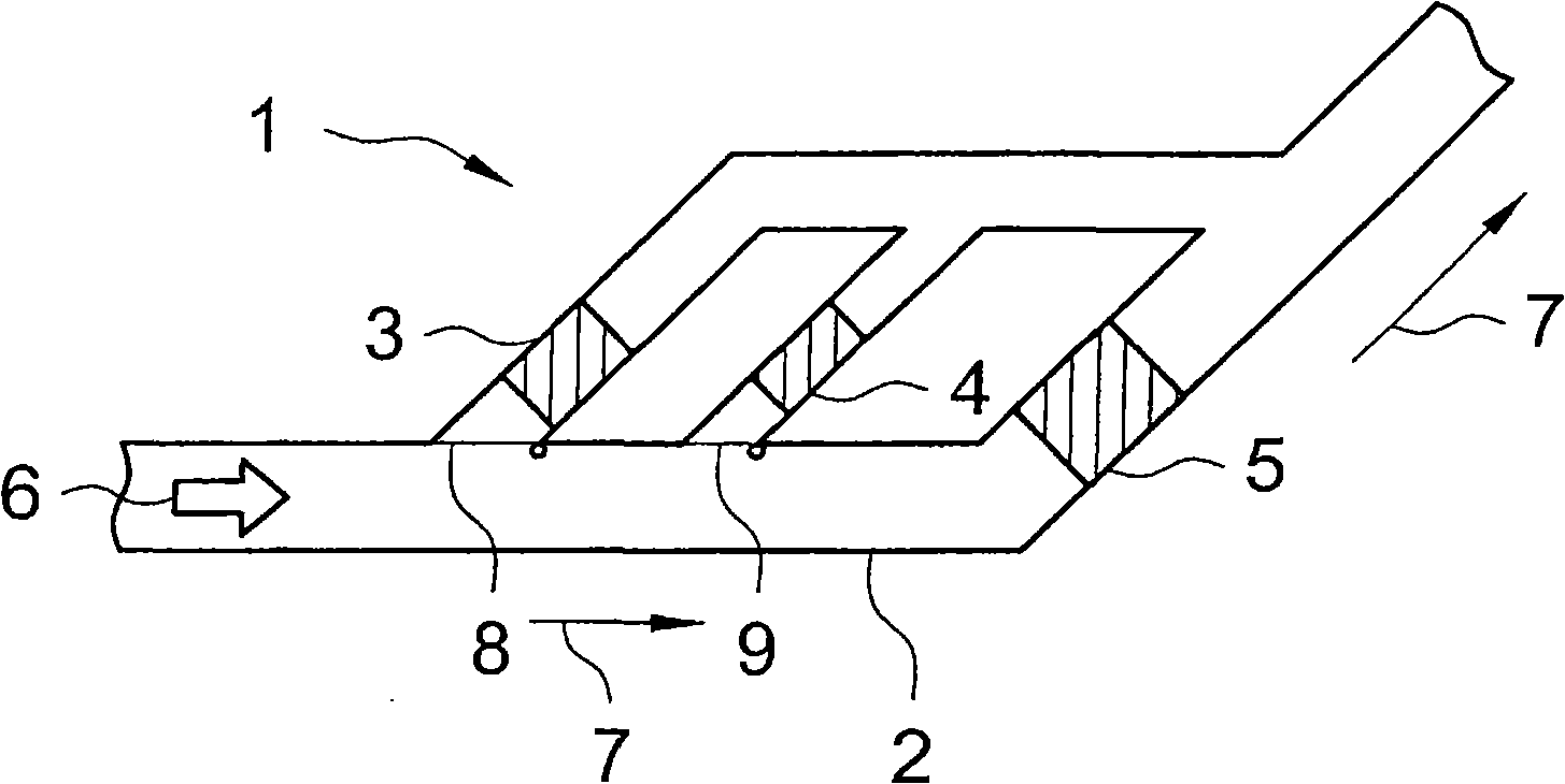
[0056] figure 1 A first exemplary embodiment of a device 1 according to the invention for treating exhaust gas 6 is shown schematically. The plant comprises an exhaust pipe 2 , a first module 3 and a second module 4 for treating the exhaust gas. In addition, an idle speed module 5 is also provided. An internal combustion engine, not shown, emits exhaust gas 6 which flows through the exhaust pipe 2 in a flow direction 7 . The first module 3 for treating exhaust gas is associated with a first connecting device 8 . In this first embodiment, the connecting device 8 comprises a pivotable flap by means of which the module 3 can be connected to the exhaust pipe 2 so that at least a part of the exhaust gas 6 can flow through the module 3 . Correspondingly, a second connecting device 9 is provided, which is associated with the second module 4 for treating the exhaust gas.

[0057] Said idle module 5 is not equipped with connection means, because even when the first connection means...


PUM


Abstract

The claimed process for treating exhaust fumes (6) from an internal combustion engine (19) in at least two modules (3, 4, 5, 17) is designed in such a way that an exhaust fume stream can be at least in part deflected depending on a load state of the internal combustion engine (19) in such a way that at least parts of the exhaust fumes (6) flow through one or more modules (3, 4, 5, 17). The claimed process and the claimed device (1) make it possible to design and operate in an advantageous manner even the exhaust fume system of large-volume internal combustion engines (19), conversion and treatment of the exhaust fumes (6) being carried out in individual modules (5, 3, 4, 17) even in no-load operation, basically at very low exhaust fume mass flow rates. The individual modules (3, 4, 5, 17) can be adapted to various load levels of the internal combustion engine (19).

Description

technical field [0001] The subject of the invention is a method and a device for treating the exhaust gas of an internal combustion engine. A particularly preferred field of application of the invention is for the treatment of exhaust gases of large displacement (groβvolumig) internal combustion engines, in particular diesel engines, especially in locomotives and watercraft. Background technique [0002] Exhaust gases from internal combustion engines contain undesirable substances which in many countries must be present in the exhaust at levels below legally established limits. This also concerns the particle concentration in the exhaust gas, which must not exceed certain values ​​in many countries. But especially with large-displacement internal combustion engines, it is sometimes difficult to comply with this limit value precisely under idling conditions. Contents of the invention [0003] It is therefore the object of the present invention to provide a method and a de...

Claims


Application Information

Patent Timeline
IPC IPC(8): F01N3/035F01N3/022F01N3/023
CPCF01N2590/02F01N2410/02F01N3/031F01N3/0222F01N3/0231F01N2410/10F01N13/04F01N13/004F01N13/011F01N2410/14F01N3/022F01N3/023F01N3/035
Inventor P·特赖贝尔
Owner EMITEC EMISSIONSTECHNIK
Why Eureka
Try Eureka