Method for operating a fuel pump

A technology of fuel pump and fuel oil, which is applied in the direction of fuel injection control, electrical control, machine/engine, etc. It can solve the problems of excessive switching loss, temperature rise of switching electronic equipment, and decrease of service life of switching electronic equipment, so as to save integral adjustment device effect

Active Publication Date: 2008-10-01
VTESCO TECH GMBH
View PDF1 Cites 11 Cited by
  • Summary
  • Abstract
  • Description
  • Claims
  • Application Information

AI Technical Summary

Problems solved by technology

Depending on the operating parameters of the system to be regulated, switching losses can significantly exceed conduction losses
A further disadvantage i

Method used


Image

  • Method for operating a fuel pump
  • Method for operating a fuel pump

Examples


Embodiment Construction

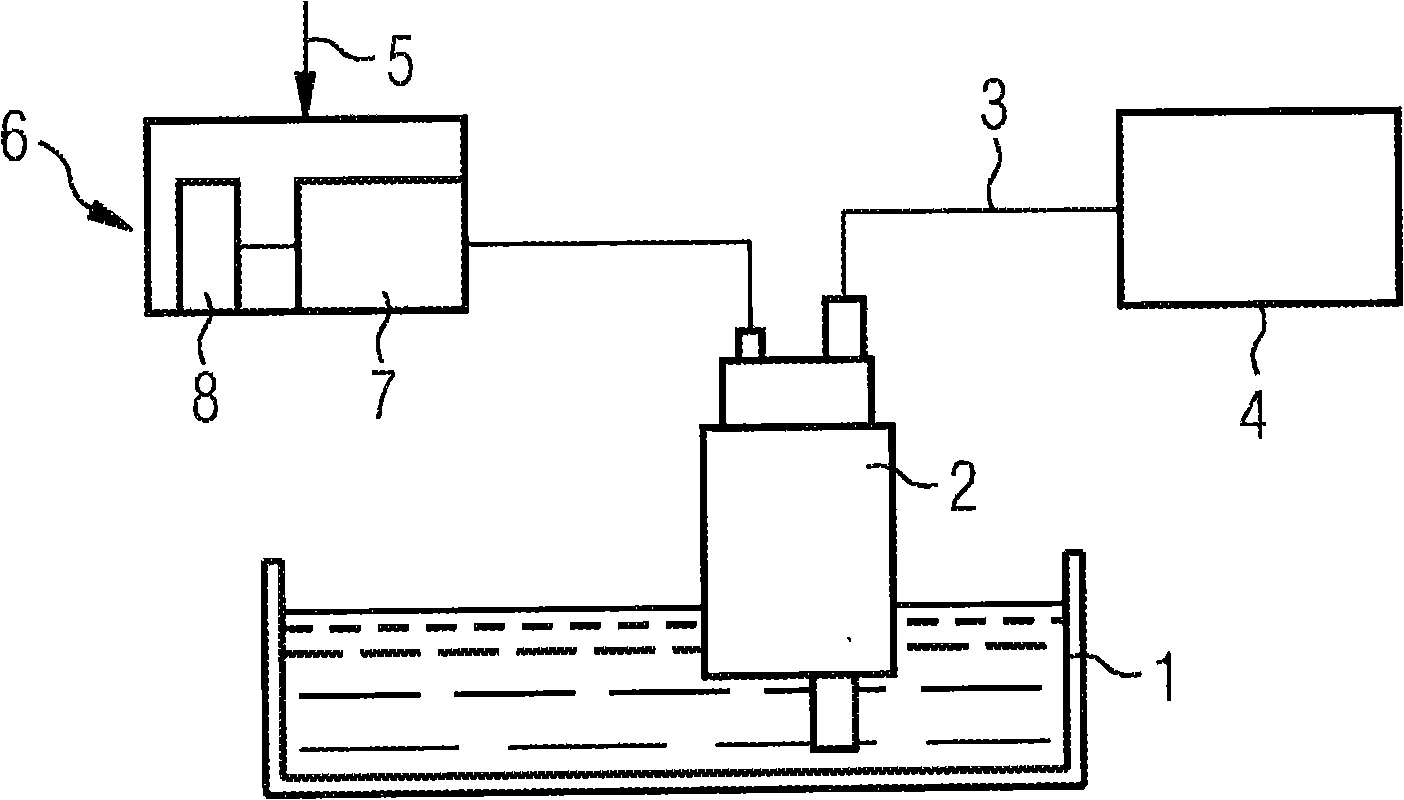
[0020] figure 1 A fuel tank 1 of a motor vehicle, not further shown, is shown schematically. A fuel pump 2 is arranged in the fuel tank 1 and delivers fuel from the fuel tank 1 to an internal combustion engine 4 of the motor vehicle via a feed line 3 . An electronic signal 5 obtained in a known manner is transmitted to the control electronics 6 for the fuel pump 2 , which is a criterion for the momentary fuel demand on the internal combustion engine 4 . Control electronics 6 includes a pulse generator 7 , which supplies the current for fuel pump 2 to fuel pump 2 in the form of pulses. The pulses are delivered with a constant amplitude, the pulse width being the criterion for the electrical energy delivered. The electronic control signal 6 is arranged in the shown figure outside the fuel tank 1 , for example as a component of the engine control system. However, it is also conceivable to arrange the control electronics 6 on or in the fuel tank 1 , for example on a flange or i...


PUM


Abstract

The invention relates to a method for operating a fuel pump in order to guide fuel from the fuel container of an internal combustion engine, wherein the electric energy, which is in the form of pulses, is periodically guided to the fuel pump and the duration of the pulses is controlled according to the fuel required by the internal combustion engine. The frequency of the pulses is controlled in such a manner that, in the event of low pump capacity of the fuel pump, the frequency is controlled to a higher level than in the even of a high pump capacity.

Description

technical field [0001] The invention relates to a method for operating a fuel pump such that fuel is delivered from a fuel tank to an internal combustion engine, wherein pulsed electrical energy is supplied to the fuel pump and the duty cycle is adjusted in dependence on the fuel demand of the internal combustion engine. Such adjustable fuel pumps are installed, in particular, in the fuel tank of a motor vehicle. Background technique [0002] A fuel tank which is electronically regulated according to the fuel requirement is known from DE 43 02 383 A1. Here, electrical energy is pulsed to the fuel pump, wherein the duty cycle is changed as a direct function of the regulated output signal of the air mass sensor, wherein the sensor generates a signal as a function of the position of the throttle valve, which The position is the standard for the fuel requirements of internal combustion engines. This method of regulated, pulsed supply of electrical energy is also known as pulse...

Claims


Application Information

Patent Timeline
IPC IPC(8): F02D41/30
CPCF02D41/3082F02D2041/2027
Inventor 罗尔夫·格拉夫
Owner VTESCO TECH GMBH
Why Eureka
Try Eureka