Indoor gas pipeline leakage protecting method and apparatus

An internal gas and pipeline technology, applied in the field of indoor gas pipeline leakage protection methods and devices, can solve problems such as slow gas leakage, safety accidents, and no indoor gas pipelines, and achieve reliable safety protection and reliable leakage protection. Effect

Inactive Publication Date: 2008-10-08
HUAZHONG UNIV OF SCI & TECH +1
View PDF0 Cites 10 Cited by
  • Summary
  • Abstract
  • Description
  • Claims
  • Application Information

AI Technical Summary

Problems solved by technology

[0002] At present, there is generally no special safety control device for indoor gas pipelines. It mainly adds odor to the gas. If there is a leak, it is generally judged by people's sense of smell. However, in many cases, if there is no one at home, it will easily cause a major safety accident.
The existing anti-leakage technology mainly has the following aspects. One is the leakage alarm or device, which senses the gas leakage through the combustible gas sensitive element. The cost is often too high, and the performance of the low-cost one is often unreliable. In addition, the sampling point position of the sensitive element sometimes cannot effectively

Method used


Image

  • Indoor gas pipeline leakage protecting method and apparatus
  • Indoor gas pipeline leakage protecting method and apparatus

Examples


Embodiment 1

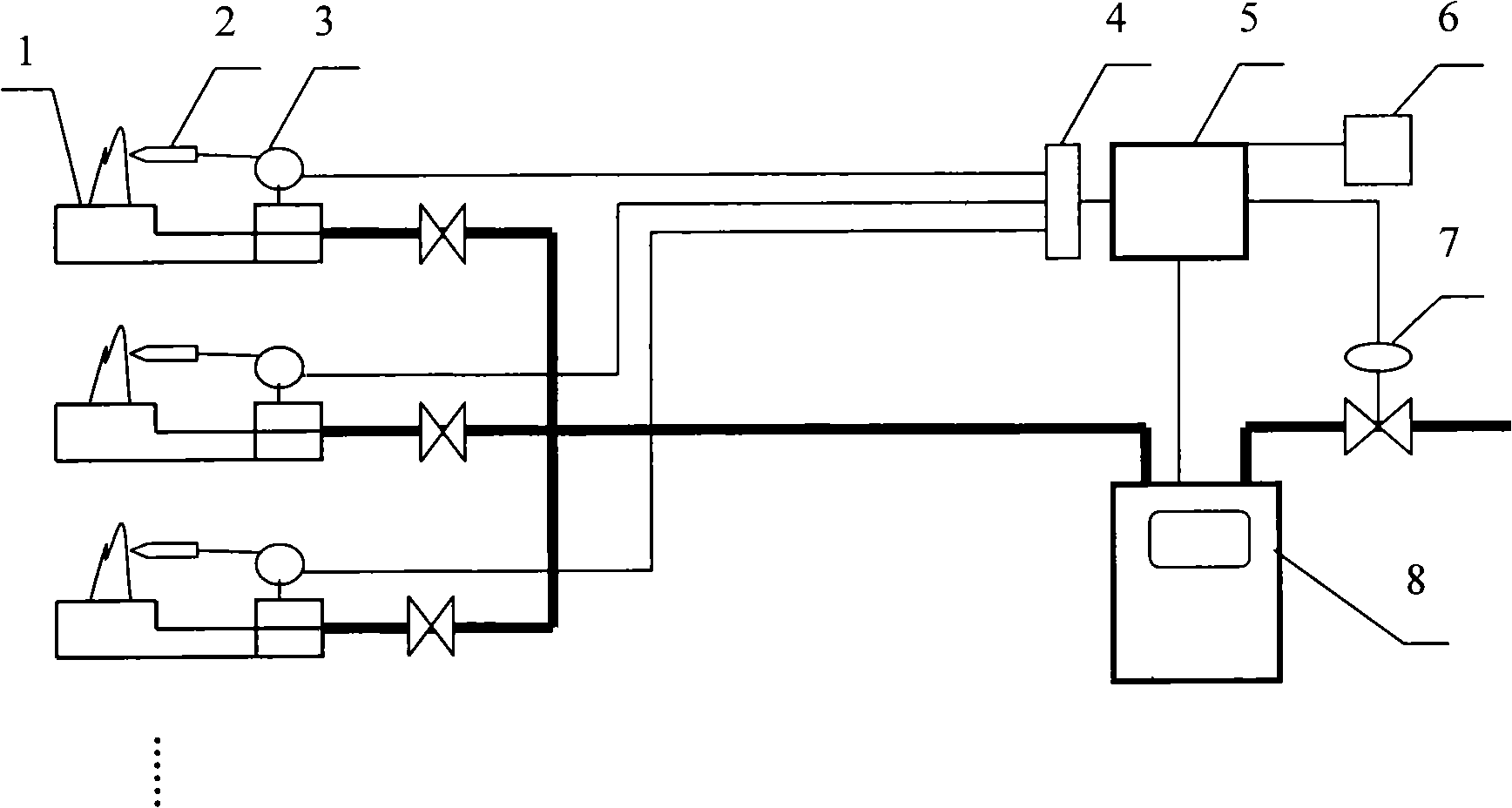
[0017] Such as figure 1 As shown, the indoor gas pipeline leakage protection device provided by the present invention includes a flame signal acquisition module 4 , a control circuit 5 , a normally closed solenoid valve 7 , an alarm 6 and a flow signal acquisition module 8 . In this example, the flame signal acquisition module 4 uses a potential signal detection unit.

[0018] The flow signal acquisition module 8 is installed on the gas inlet pipe, and is used to obtain the flow information on the gas inlet pipe, which may be the output signal of the gas meter or the signal provided by other gas flow sensors.

[0019] The potential signal detection unit is connected to the input end of the solenoid valve 3 for flameout protection of the gas appliance through wires, and obtains the potential signal of the solenoid valve 3 to obtain the working state information of the gas appliance. The normally closed solenoid valve 7 and the flow signal acquisition module 8 are installed on ...

Embodiment 2

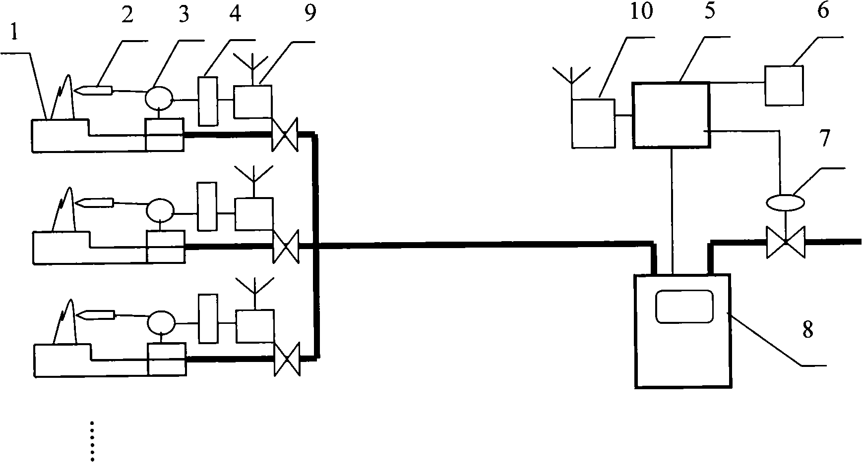
[0024] Such as figure 2 As shown, will figure 1 The wired transmission mode of the flame detection signal in the shown system is changed to wireless transmission. For this reason, a dedicated data transmission module 9 is installed on each gas appliance, and the flame detection signal is sent out in an encrypted manner. The burning appliance uses the same encrypted signal, and a data receiving module 10 corresponding to the data transmission module 9 is also installed in the control circuit, which is specially used for receiving predetermined encrypted signals.

[0025] This system does not require indoor wiring, which is more suitable for the transformation of old users.


PUM


Abstract

The invention provides a gas pipe line leakage protection method comprising steps of: acquiring flame signal of gas kitchen ranges real time; extracting flow capacity information of gas house lead in pipeline real time; shutting down the house lead in gas pipeline and alarming when flow capacity information exist on the gas meter and non flame signal of the gas kitchen ranges in 10-30s. according to invention, the device comprises a flame signal capturing module, a control circuit, a normally closed solenoid valve, a flow capacity signal capturing module and a alarm; the control circuit acquires working condition information of the gas kitchen ranges with the flame signal capturing module, flow capacity information of the house lead in pipeline is acquired by the flow capacity signal capturing module, when the flow capacity signal capturing module has flow capacity information and the flame signal capturing module has not potential signal, the control circuit separately sends signal to the normally closed solenoid valve and the alarm. The invention resolves problem that possible leakage of the indoor gas pipe system may carry potential safety hazard, which effectively protects users, and manpower is saved, also operating cost of city gas pipeline is reduced.

Description

technical field [0001] The invention belongs to pipeline gas safety technology, and in particular relates to an indoor gas pipeline leakage protection method and a device thereof. Background technique [0002] At present, there is generally no special safety control device for indoor gas pipelines. The main thing is to add odor to the gas. If there is a leak, it is generally judged by people's sense of smell. However, in many cases, if there is no one at home, a leak will easily cause a major safety accident. The existing anti-leakage technology mainly has the following aspects. One is the leakage alarm or device, which senses the gas leakage through the combustible gas sensitive element. The cost is often too high, and the performance of the low-cost one is often unreliable. In addition, the sampling point position of the sensitive element sometimes cannot effectively sense the leakage, and its safety cannot be guaranteed at all; there is another technology that is over-cur...

Claims


Application Information

Patent Timeline
IPC IPC(8): F17D5/02F24C3/12
Inventor 王劲柏刘文斌
Owner HUAZHONG UNIV OF SCI & TECH
Why Eureka
Try Eureka