

Method for testing digital oscilloscope waveform capturing rate
A digital oscilloscope, waveform capture rate technology, applied in the direction of digital variable display, instruments, measuring electricity, etc., can solve problems such as omission
- Summary
- Abstract
- Description
- Claims
- Application Information
AI Technical Summary
Problems solved by technology
Method used
Image

Examples
Embodiment Construction
[0022] The following describes preferred specific embodiments of the present invention in conjunction with the accompanying drawings. It is to be noted that similar components are given similar reference numerals even though they appear in different drawings. In the following description, when a detailed description of known functions and designs employed may obscure the subject matter of the present invention, these descriptions will be omitted here.
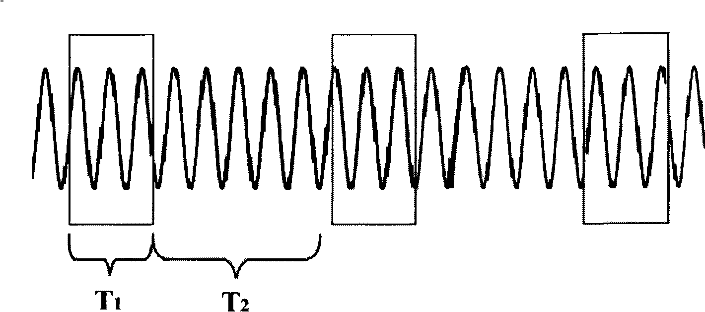
[0023] figure 1 It is a schematic diagram of digital oscilloscope waveform acquisition and processing. In the figure, the digital oscilloscope first collects the waveform, and the collection time is T 1 . The digital oscilloscope then performs signal processing on the collected waveform data. During this period, the digital oscilloscope cannot capture the signal, and the dead time is T 2 .
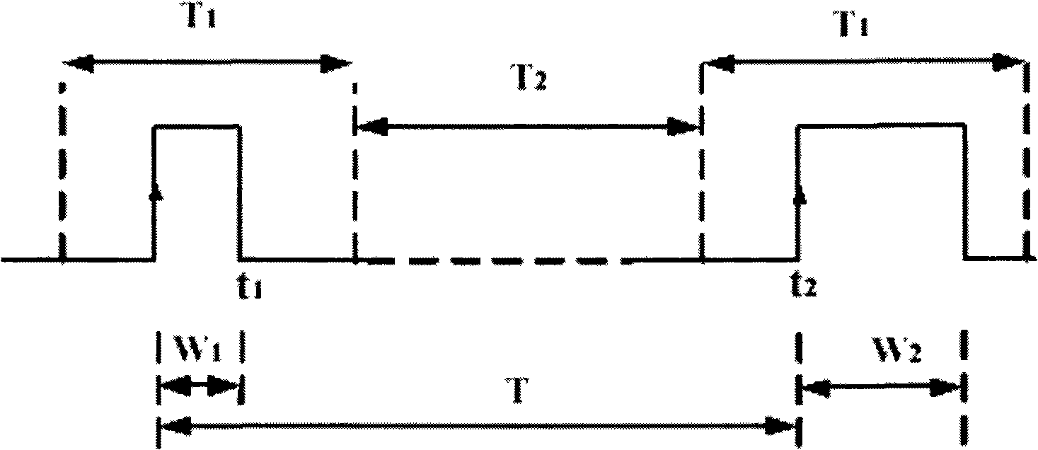
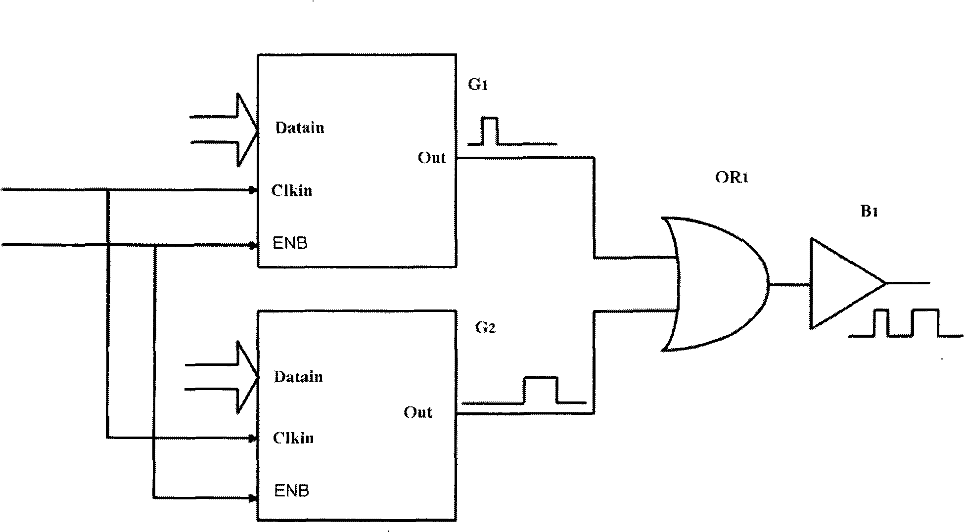
[0024] figure 2 It is a principle diagram of a specific embodiment of the testing method of the waveform capture rate of the presen...
PUM
 Abstract
Description
Claims
Application Information