Sound-heat liquid magnetofluid AC generating system

A technology for a power generation system and an alternator, which is applied to electrical components, electromechanical devices, etc., can solve the problems of high engine cost, complex thermoacoustic engine, and high cost of magnetic fluid power generation system. Difficulty and cost, the effect of low working frequency

Active Publication Date: 2008-10-08
TECHNICAL INST OF PHYSICS & CHEMISTRY - CHINESE ACAD OF SCI
View PDF1 Cites 25 Cited by
  • Summary
  • Abstract
  • Description
  • Claims
  • Application Information

AI Technical Summary

Problems solved by technology

[0004] The purpose of the present invention is to overcome the complexity of the thermoacoustic engine and the cost of the engine produced by the existing thermoacoustic magnetic fluid AC power generation system directly using liquid metal ferrofluid as the working medium, including the thermoacoustic engine also using the same liquid metal ferrofluid as the working medium High, the high cost of the entire magnetic fluid power generation system, to provide an improved thermoacoustic liquid magnetic fluid power generation system

Method used


Image

  • Sound-heat liquid magnetofluid AC generating system
  • Sound-heat liquid magnetofluid AC generating system
  • Sound-heat liquid magnetofluid AC generating system

Examples


Embodiment 1

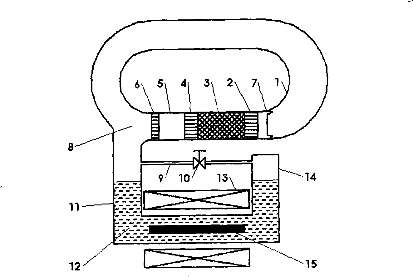
[0037] Such as figure 1 As shown, the thermoacoustic power generation system of this embodiment includes a traveling wave thermoacoustic engine and a liquid magnetic fluid generator. The working medium in the thermoacoustic engine is gas such as nitrogen, and the working medium in the liquid magnetic fluid engine is liquid magnetic fluid such as Gallium metal is liquid at room temperature. The traveling wave thermoacoustic engine includes a feedback tube 1 connected in sequence to form a traveling wave circuit, a heat exchanger 2 at the room temperature end, a regenerator 3, a heater 4, a thermal buffer tube 5, and a heat exchanger 6 at the room temperature end to eliminate The elastic membrane 7 of the loop direct current, the tee 8 and each annular connecting pipe; the liquid magnetic fluid generator is a liquid magnetic fluid alternator installed at the tee 8. When the heat enters the generator system from the heater 4, a temperature difference appears between the two end...

Embodiment 2

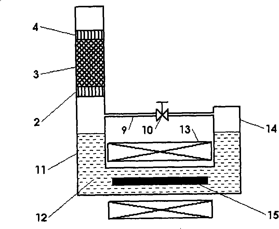
[0040] Such as figure 2 As shown, the thermoacoustic generator system in Embodiment 1 can also use a standing wave thermoacoustic engine to generate pressure fluctuations to drive liquid magnetic fluid movement; the standing wave thermoacoustic engine includes a heater 4, a plate stack 3, and a room temperature The end heat exchangers 2 are connected sequentially, and the plate stack 3 is functionally the same as the regenerator, and also produces a temperature gradient at both ends. When heat enters the engine system from the heater 4 , a temperature difference appears at both ends of the plate stack 3 , and a temperature gradient is established in the axial direction of the plate stack 3 . When the temperature gradient is greater than the critical temperature gradient, the standing wave thermoacoustic engine generates self-excited oscillations, converting thermal energy into mechanical energy, which is provided to the generator to drive the magnetic fluid movement to cut th...

Embodiment 3

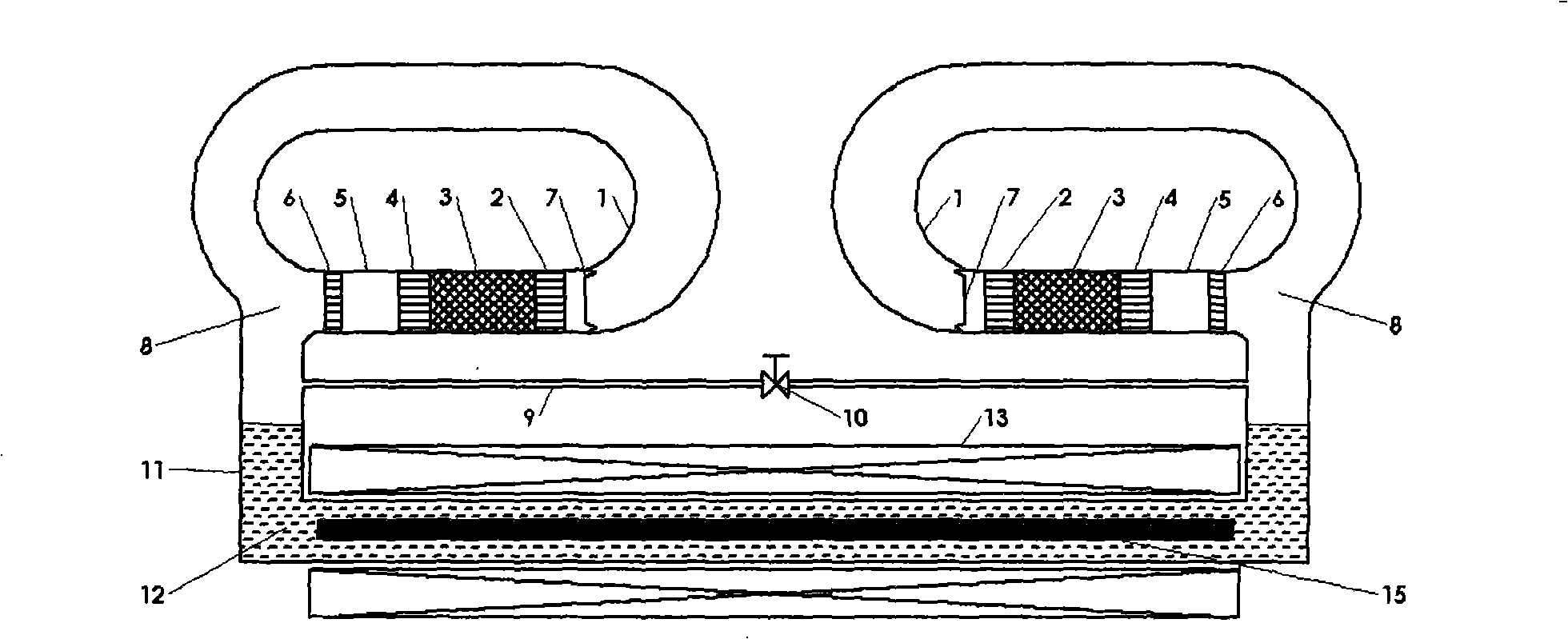
[0043] Such as image 3 As shown, on the basis of Embodiment 1, a row of wave-type thermoacoustic engines are respectively connected to both ends of the U-shaped electrically insulating flat pipe 11, thereby obtaining greater pressure fluctuations and increasing the movement speed of the magnetic fluid 12. , to improve the performance of the magnetic fluid generator. The structure and others of the traveling wave thermoacoustic engine are the same as those in Embodiment 1.

[0044] In this embodiment, a traveling-wave thermoacoustic engine in the form of a loop is used. Those skilled in the art can easily understand that a coaxial traveling-wave thermoacoustic engine or a standing-wave thermoacoustic engine may also be used. The structure of the coaxial traveling wave thermoacoustic engine can be the same as that of the coaxial traveling wave thermoacoustic engine in embodiment 1, and the structure of the standing wave thermoacoustic engine can be the same as that of embodime...


PUM


Abstract

The invention provides a thermo-acoustic liquid state magnetic fluid alternative electric generation system which comprises a thermo-acoustic motor and a liquid state magnetic fluid alternating current ganerator, the resonatron of the thermo-acoustic motor is coupled on one opening end of the pipe of the liquid state magnetic fluid alternating current ganerator for containing the liquid state magnetic fluid, the pipe is arranged in the magnetic field to make the liquid state magnetic fluid cut the magnetic force line to generate electric energy when flowing in the pipe, the pipe comprises an output electrode for outputing the generated electric energy, which is characterized in that, the working substance of the thermo-acoustic motor is gas working substance. The invention reduces manufacturing difficulty and cost of the prior electric generation system, and the working frequency is suitable, the efficiency is high.

Description

technical field [0001] The invention relates to a liquid magnetic fluid power generation system, in particular to a liquid magnetic fluid alternating current power generation system driven by a thermoacoustic engine. Background technique [0002] Thermoacoustic engines have the advantages of good energy adaptability, no moving parts, and high reliability. The use of thermoacoustic engines can efficiently convert various forms and grades of heat sources, including solar energy, geothermal heat, and industrial waste heat, into mechanical work (acoustic work). The magnetofluid AC power generation system driven by the thermoacoustic engine uses the pressure fluctuation generated by the thermoacoustic engine to push the liquid magnetic fluid to move in the magnetic field. electrical energy. [0003] In U.S. Patent No. 4,599,551, a thermoacoustic engine-driven magnetic fluid alternating current power generation system is disclosed. It is driven by two opposing standing wave ther...

Claims


Application Information

Patent Timeline
Patent Type & Authority Applications(China)
IPC IPC(8): H02K44/08H02K44/18
Inventor 罗二仓吴张华戴巍胡剑英
Owner TECHNICAL INST OF PHYSICS & CHEMISTRY - CHINESE ACAD OF SCI
Why Eureka
Try Eureka