
Hydraulic control device for engine

A control device and engine technology, applied in the direction of engine components, machines/engines, engine lubrication, etc., can solve the problems of increased load, deterioration of starting performance, and the flywheel cannot reach the minimum speed of engine starting, and achieves reduction of hydraulic pressure. Effect

Inactive Publication Date: 2008-10-15
TOYOTA JIDOSHA KK
View PDF2 Cites 18 Cited by
  • Summary
  • Abstract
  • Description
  • Claims
  • Application Information

AI Technical Summary

Problems solved by technology

However, since the viscosity of the oil becomes higher when the temperature is low, the flow resistance of the oil flowing through the oil passage increases, so the load applied to the oil pump increases, which is expressed as a reaction force against the driving force of the starter motor
Therefore, the flywheel cannot reach the minimum speed to start the engine, which will lead to poor starting performance

Method used


Image

  • Hydraulic control device for engine
  • Hydraulic control device for engine
  • Hydraulic control device for engine

Examples


no. 1 example

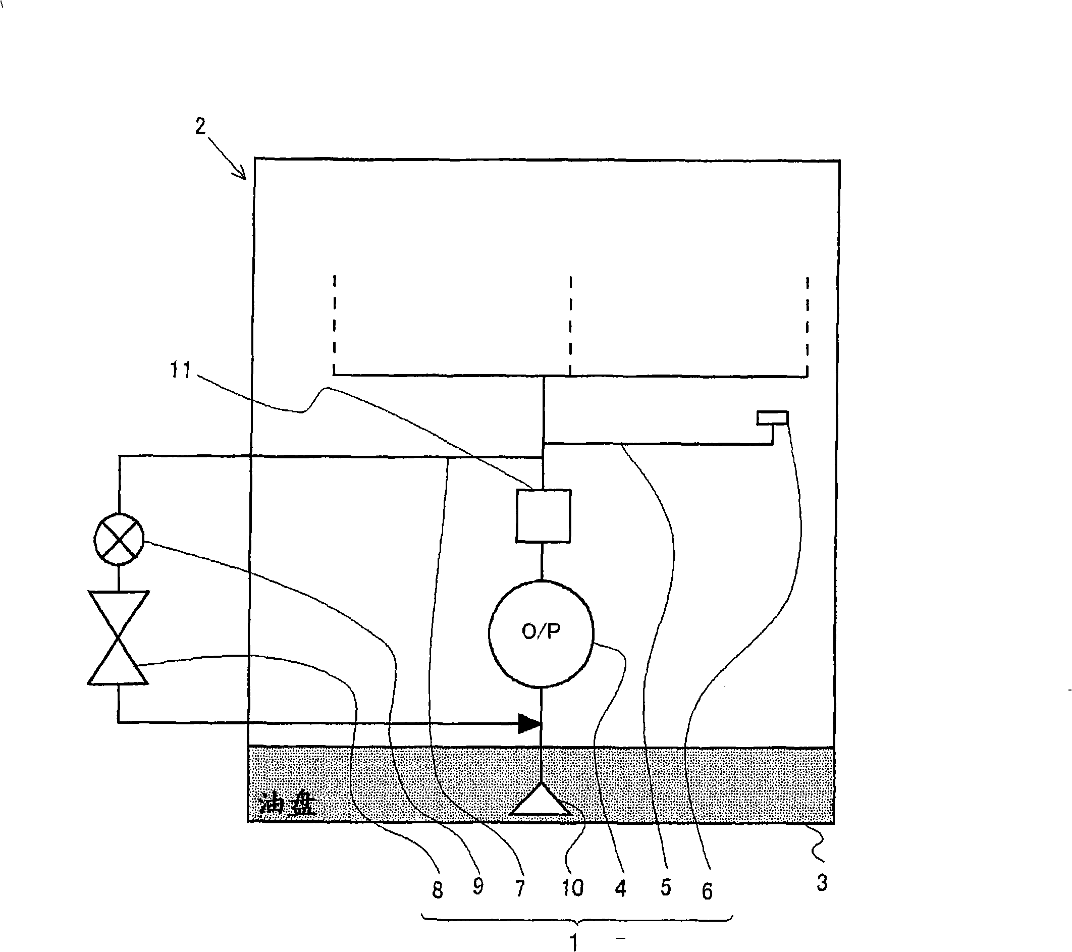
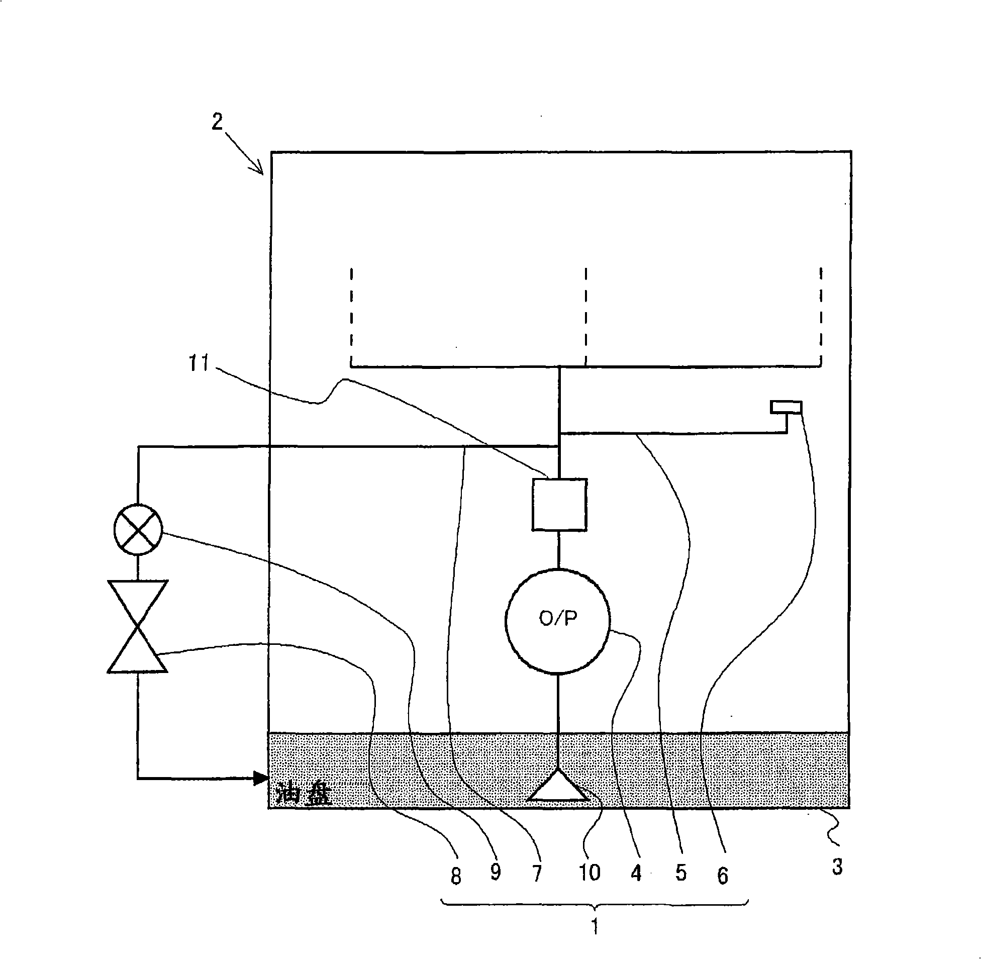
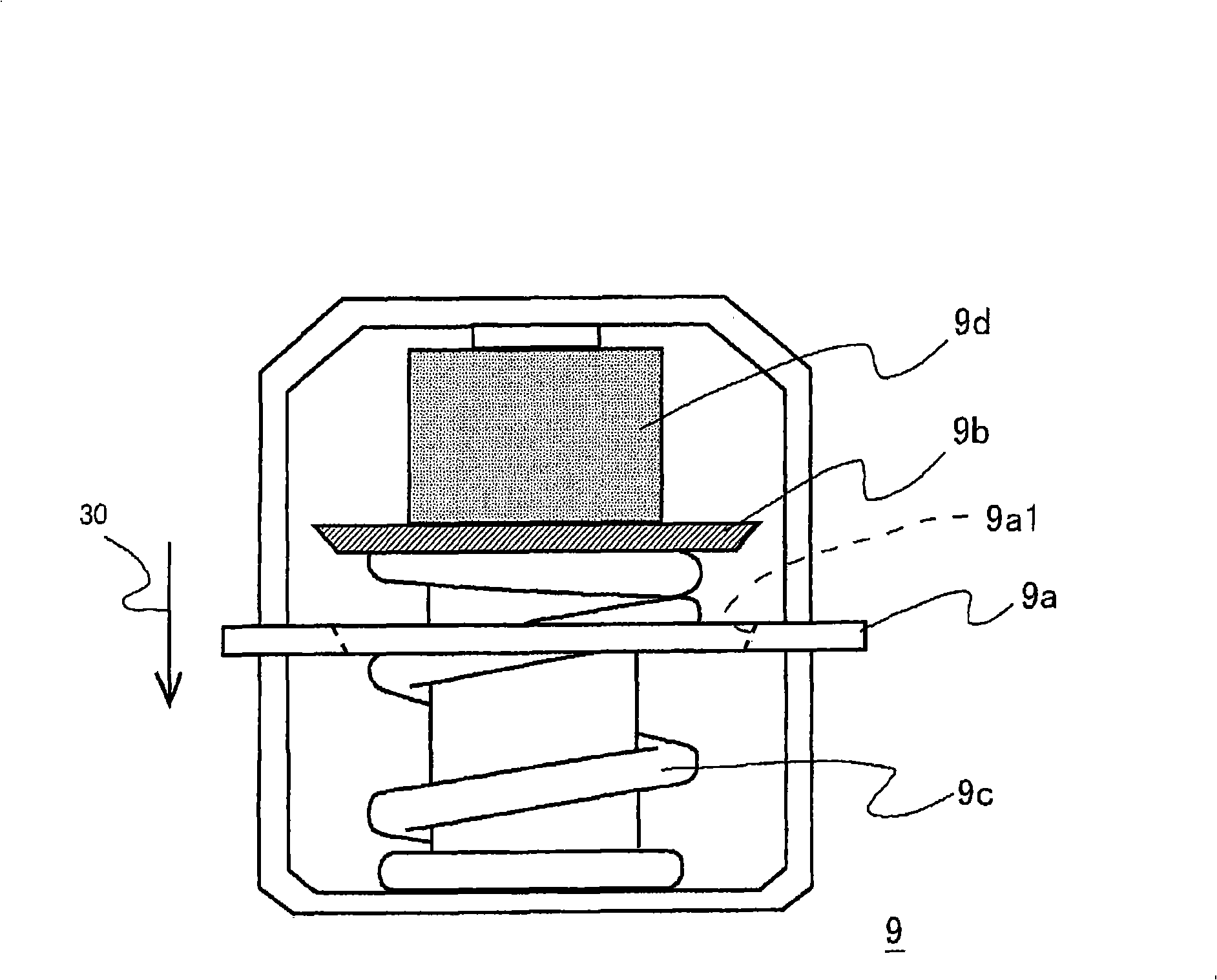
[0034] figure 1is a schematic diagram showing a schematic structure of an engine 2 equipped with a hydraulic control device 1 of the present invention. This hydraulic control device 1 includes an oil pump 4 that sucks oil from an oil pan 3 by the rotation of the crankshaft; when the hydraulic pressure of the oil that has been sucked by the oil pump 4 reaches the valve opening pressure Qa, it opens and sends the oil to the piston ( not shown) a piston nozzle 6 for injection; a pressure reducing valve 8 arranged on an oil return path 7 different from the oil injection path 5 and opened when the hydraulic pressure of the oil which has been sucked by the oil pump 4 reaches the valve opening pressure Qb; and the arrangement Switching valve 9 on oil return path 7. The oil pan 3 corresponds to an oil tank in the present invention. A strainer 10 is disposed on an upstream end portion of the oil pump 4 . In addition, the downstream end of the oil return path 7 is connected to the oi...

no. 2 example

[0043] Below, refer to Figure 4 A second embodiment of the present invention will be described. Figure 4 The hydraulic control device 20 shown differs from the hydraulic control device 1 of the first embodiment in that, in the hydraulic control device 1 of the first embodiment, the switching valve 9 is a valve that performs opening and closing by detecting the temperature of oil. In contrast to this, in the hydraulic control device 20 of the second embodiment, the switching valve 21 employs an electromagnetic solenoid controlled by the ECU 22 that executes opening and closing commands based on data obtained from the sensor group 23 . The other structures are not different from those of the hydraulic control device 1 of the first embodiment, so the same reference numerals are assigned to the same parts in the drawings, and their descriptions are omitted.

[0044] The switching valve 21 of this hydraulic control device 20 performs opening and closing operations based on the e...


PUM


Abstract

The present invention relates to a hydraulic control device (1) having an oil pump (4) for sucking oil from an oil pan (3) by rotation of a crankshaft, a piston jet (6) opened when the pressure of the oil sucked by the oil pump (4) reaches a valve opening pressure Qa and ejecting the oil through a oil ejection route (5) toward a piston, a relief valve (8) placed in an oil return route (7) and opening when the pressure of the oil sucked by the oil pump (4) reaches a valve opening pressure Qb, and a switchover valve (9) placed in the oil return path (7). The valve opening pressure Qb is set lower than the valve opening pressure Qa.

Description

technical field [0001] The present invention relates to an engine hydraulic pressure control device capable of appropriately controlling engine hydraulic pressure. Background technique [0002] Inside the engine, oil stored in an oil pan for lubrication is sucked and supplied by an oil pump, and an oil passage that supplies lubricant to each lubricated portion is formed. In addition, the oil decompression passage is connected to the oil passage downstream of the oil pump, and the oil decompression passage is provided with an oil pressure (hydraulic pressure) that opens when the pressure (hydraulic pressure) inside the oil passage accompanied by oil supplied by the oil pump becomes equal to or greater than the set pressure. Pressure reducing valve. Excess oil is returned to the oil pan, thereby regulating the maximum hydraulic pressure in the oil passage. [0003] In this regard, there has been proposed an oil pump that, during low-temperature start-up, when the viscosity o...

Claims


Application Information

Patent Timeline
Patent Type & Authority Applications(China)
IPC IPC(8): F01M1/16F01M5/00F01M1/08
CPCF01M1/16F01M1/08
Inventor 山下芳雄小林日出夫蚁泽克彦山田贤一林邦彦
Owner TOYOTA JIDOSHA KK
Learn More