Double cam linkage work-table exchange set
A technology for exchanging devices and worktables, which is applied in the direction of manufacturing tools, metal processing equipment, and metal processing machinery parts, etc., which can solve the problems of prolonged exchange time of workbenches, inaccurate mutual action coordination, unreliable movement process, etc., to achieve space occupation Small size, simple structure, and the effect of reducing processing costs
Inactive Publication Date: 2008-10-22
大连华凯机床有限公司
View PDF0 Cites 4 Cited by
- Summary
- Abstract
- Description
- Claims
- Application Information
AI Technical Summary
Problems solved by technology
The whole action process can be divided into three independent steps: workbench lifting, workbench rotation, and workbench drop, which cannot be linked. From the working process, it can be seen that the position needs to be detected at each step in the whole process of workbench exchange. This makes the exchange time of the worktable longer, and at the same time, the movement process is unreliable, and it is easy to cause inaccurate mutual actions.
Method used
View moreImage
Smart ImageViewing Examples

Examples
Embodiment Construction
Login to View More PUM
 Abstract
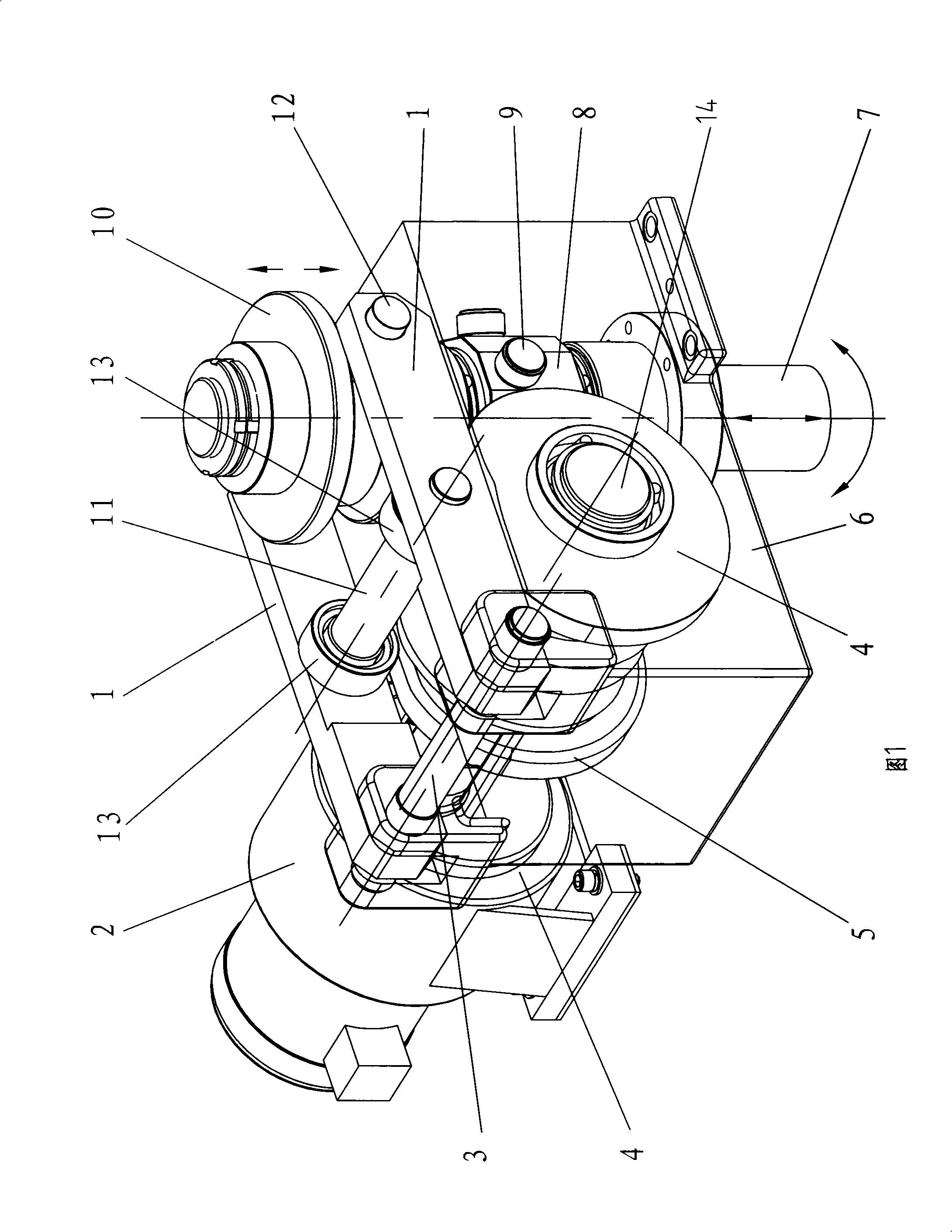
The present invention discloses a double-cam linkage worktable exchange device. The structure is that a cam shaft (14) connected with a power device is supported on a bracket (6); the cam shaft (14) is fixed with an elevating cam (4); one end of an elevating rod (1) matched with the elevating cam (4) is axially connected with the bracket (6) and the other end of an elevating lever (1) is arranged below a worktable round disc (10) which is fixedly connected with a rotating shaft (7); a rotating shaft sleeve (8) connected with the axial slide key of the rotating shaft (7) is sheathed outside the rotating shaft (7); the rotating shaft sleeve (8) is provided with a rotating idler wheel (9) which is matched with a rotating cam (5) arranged on the cam shaft (14). The present invention ensures that the lifting, the rotating and the falling of the worktable of the horizontal processing center are driven by a power mechanism and achieves the linkage in the whole process. Each motion is mutually and accurately matched with each other and the exchange process is rapid, safe, flexible and reliable, thus reducing the processing cost of the workpiece. The double-cam linkage worktable exchange device of the present invention is simple in structure and small in occupied space.
Description
Double-cam linkage table exchange device technical field The invention relates to a worktable exchanging device on mechanical processing equipment, in particular to a double-cam linkage workbench exchanging device for a horizontal machining center. Background technique The workbench on the horizontal machining center needs to have the exchange action of lifting and rotating, which is mainly completed by two driving mechanisms, one is a lifting mechanism and the other is a rotating mechanism. The lifting mechanism that controls the worktable is driven by a hydraulic cylinder connected to the hydraulic control device. The rotation of the worktable after it is lifted can be driven by a cam driven by a geared motor or driven by a hydraulic rotary cylinder. The whole action process can be divided into three independent steps: workbench lifting, workbench rotation, and workbench drop, which cannot be linked. From the working process, it can be seen that the position needs to be ...
Claims
Login to View More Application Information
Patent Timeline
 Patent Type & Authority Applications(China)
IPC IPC(8): B23Q1/25B23Q1/64
Inventor 李全普王坤邵连英郑光明
Owner 大连华凯机床有限公司

PatSnap Eureka turns technology decisions into work you can execute. Powered by our Innovation Knowledge Graph, it runs expert workflows across engineering, life sciences, materials and intellectual property. Get your review-ready output in minutes.


