Retardation compensation element and manufacturing method of the same

A technology for compensating components and manufacturing methods, applied to optical components, polarizing components, optics, etc., can solve the problems of reducing contrast and unavoidable degradation of display image quality, and achieve the effect of improving phase difference compensation

Inactive Publication Date: 2008-10-22
FUJI PHOTO OPTICAL CO LTD
View PDF2 Cites 0 Cited by
  • Summary
  • Abstract
  • Description
  • Claims
  • Application Information

AI Technical Summary

Problems solved by technology

As a result, a part of the polarized light component passes through the cross-Nicol-type polarizing plates arranged on the exit surface side and acts in a direction to brighten the black level on the screen, thereby lowering the contrast ratio.
Moreover, when the liquid crystal molecules in the liquid crystal layer are aligned horizontally or in the middle, it is unavoidable to reduce the quality of the displayed image due to the difference in birefringence caused by the angle of light incident on the liquid crystal layer.

Method used


Image

  • Retardation compensation element and manufacturing method of the same
  • Retardation compensation element and manufacturing method of the same
  • Retardation compensation element and manufacturing method of the same

Examples


Embodiment Construction

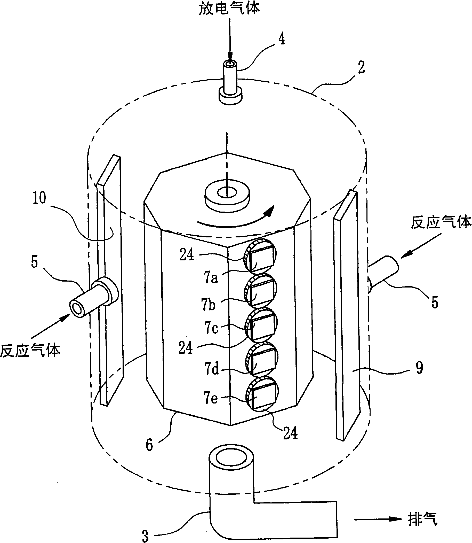
[0032] The phase difference compensation element of the present invention is composed of, for example, figure 1 The sputtering device shown is fabricated. The sputtering device, although its structure is basically the same as Figure 7 The conventional apparatus shown is the same, but a mechanism for rotating the substrate 7 around its normal is provided on the drum 6 supporting the substrate 7 . Also, a rotatable substrate holder 24 is provided on the outer peripheral surface of the drum body 6, and five substrates 7a-7e are held by the substrate holder 24, and these substrates 7a-7e can surround the substrate holder 24 by 90° as the substrate holder 24 rotates. The normal is rotated 90°. In addition, the 90° rotation direction may be either clockwise or counterclockwise.

[0033] The other constitution of this sputtering device and Figure 7 The conventional device shown is the same, and the target material 9 uses Nb which forms a high refractive index. 2 o 5 The film-f...


PUM


Abstract

This invention provides a phase difference compensating component and manufacturing method thereof, wherein the phase difference compensating effect generated by a phase difference compensation layer with multi-layer structure where films with different reflection ratio are alternately laminated is improved; substrates (7a to 7e) are kept by a rotary drum body (6); the phase difference compensating layer is enabled to spattered to form film by utilizing the rotary drum body (6), at the same time utilizing a spattering particles from a target materials (9, 10). After a first unit equal to a half of the phase difference compensation layer is formed a film, a substrate bracket (24) is rotated so as to enable each substrate (7a to 7e) to rotate 90 degrees surrounding a normal. Then a second layer for composing the rest half of the phase difference compensating layer is formed a film by using the same mode.

Description

technical field [0001] The invention relates to a phase difference compensating element used in a liquid crystal display panel and a manufacturing method thereof. Background technique [0002] Liquid crystal display panels are often used as direct-view display devices for television receivers and various devices, and can also be used as image display devices for liquid crystal projectors. For liquid crystal display panels, a plurality of liquid crystal cells are arranged in a predetermined pattern corresponding to the arrangement of pixels. According to the difference in the operation mode of the liquid crystal molecules sealed in the liquid crystal cells, the following types are known, namely TN (Twisted Nematic) type, VAN ( Vertical Alignment Nematic) type, IPS (In-Plane Switching) type, OCB (Optically Compensatory Bend) type, etc. [0003] In a liquid crystal display panel used in a liquid crystal projector, in order to improve the contrast of an image on the screen, a t...

Claims


Application Information

Patent Timeline
Patent Type & Authority Applications(China)
IPC IPC(8): G02B5/30G02F1/13363
CPCG02B5/3083G02F1/13363
Inventor 金谷元隆
Owner FUJI PHOTO OPTICAL CO LTD
Why Eureka
Try Eureka