Method for precisely marking arriving time of initial wave of fault generated traveling waves for electricity transmission line
A technology of fault traveling waves and transmission lines, applied to fault locations, emergency protection circuit devices, electrical components, etc., can solve problems such as inaccurate sampling points and inability to accurately locate the wave head time
- Summary
- Abstract
- Description
- Claims
- Application Information
AI Technical Summary
Problems solved by technology
Method used
Image
Examples
Embodiment 1
[0099] This example is the traveling wave current analysis of the phase C fault of Hongqiao Changhongzhan II of Qujing Power Supply Bureau of Yunnan Power Grid at 20:43:25 on May 29, 2008.
[0100] (1) When a fault occurs in the line, the fault traveling wave analysis device is activated to perform fast and high sampling rate (1MHz) wave recording;
[0101] (2) Truncating the traveling wave data file, see Figure 5 , select the 2ms data time window before and after the initial wave head;
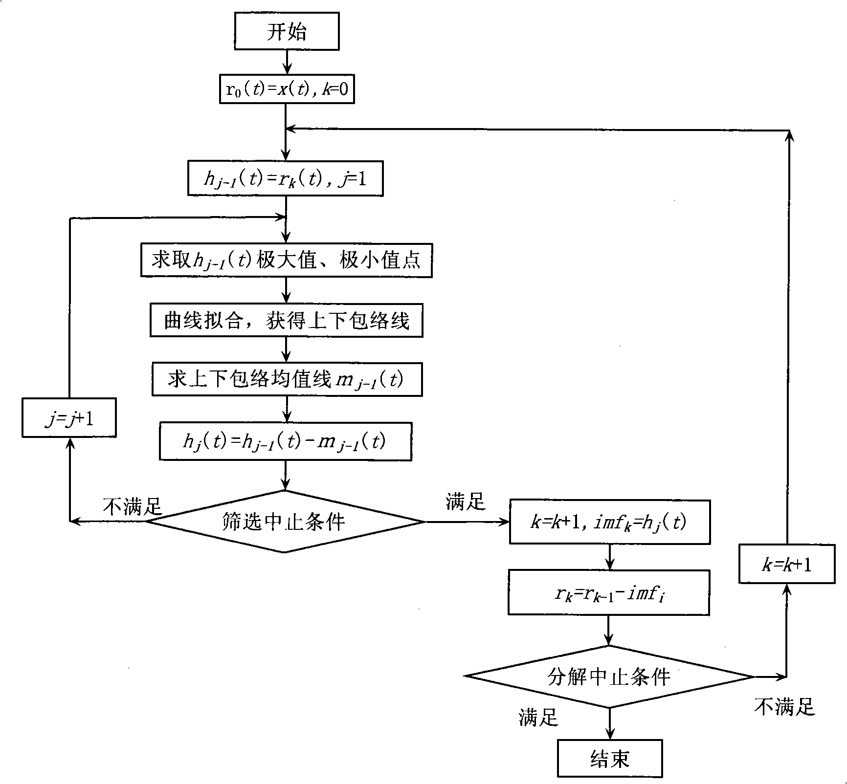
[0102] (3) For truncated data press figure 1 The process shown in the figure performs EMD decomposition to obtain the first few IMF components. For the results of EMD decomposition, see Figure 5 (IMF1), (IMF2), (IMF3) curves;
[0103] (4) Select IMF 1 For the object of investigation,
[0104] According to formula (1)
[0105] Y ( t ) = 1 π ∫ - ...
Embodiment 2
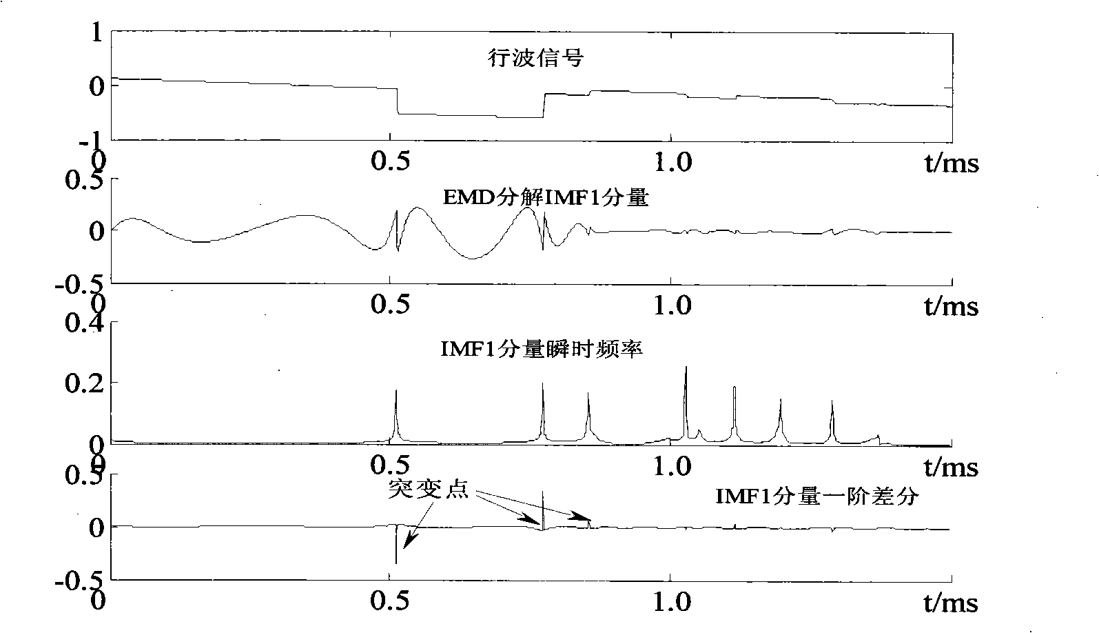
[0114] This example is an HHT analysis of fault traveling wave simulation data, including traveling wave heads of different polarities.
[0115] (1) When a fault occurs in the line, the fault traveling wave analysis device is activated to perform fast and high sampling rate (1MHz) wave recording;
[0116] (2) Truncating the traveling wave data file, see figure 2 , select the 1.5ms data time window before and after the initial wave head;
[0117] (3) For truncated data press figure 1 The shown process performs EMD decomposition to obtain the first few IMF components;
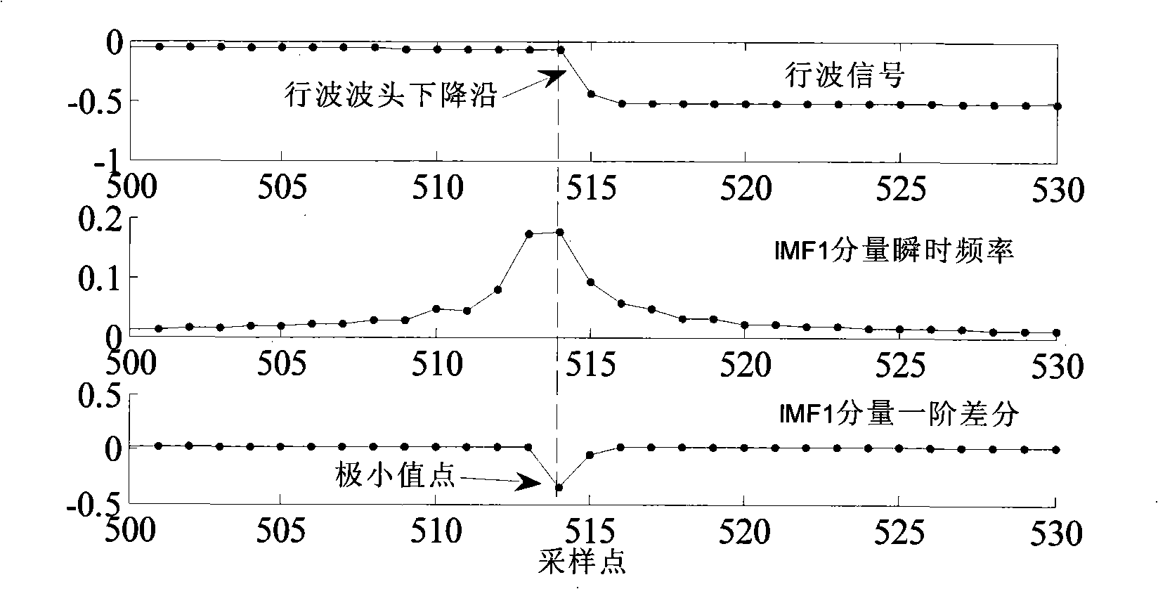
[0118] (4) Select IMF1 as the object of investigation, perform Hilbert transformation on it according to formula (1), calculate its instantaneous frequency according to formulas (5) and (6), and calculate its first-order difference, see figure 2 (IMF1 component instantaneous frequency), (IMF1 component first-order difference) curves are shown;
[0119] (5) see image 3 , the minimum value point of the firs...
PUM
 Abstract
Description
Claims
Application Information
 - R&D
- Intellectual Property
- Life Sciences
- Materials
- Tech Scout
- Unparalleled Data Quality
- Higher Quality Content
- 60% Fewer Hallucinations
Browse by: Latest US Patents, China's latest patents, Technical Efficacy Thesaurus, Application Domain, Technology Topic, Popular Technical Reports.
© 2025 PatSnap. All rights reserved.Legal|Privacy policy|Modern Slavery Act Transparency Statement|Sitemap|About US| Contact US: help@patsnap.com


