Customer signal transmission method in optical transmitting network and related equipment
A client signal and optical transport network technology, applied in the field of optical communication, can solve the problem of lack of flexible mapping methods for CBR transparent transmission, and achieve the effect of enhancing flexible adaptability and improving utilization rate
Active Publication Date: 2008-10-22
HUAWEI TECH CO LTD
View PDF0 Cites 50 Cited by
- Summary
- Abstract
- Description
- Claims
- Application Information
AI Technical Summary
Problems solved by technology
Compared with client signals of many rate levels, the OTN system only defines transmission channels of fixed rate levels and limited CBR mapping methods, and lacks flexible mapping methods to adapt to CBR transparent transmission of client signals of different rate levels
Method used
View moreImage
Smart ImageViewing Examples
Examples
no. 1 example
Login to View More PUM
 Abstract
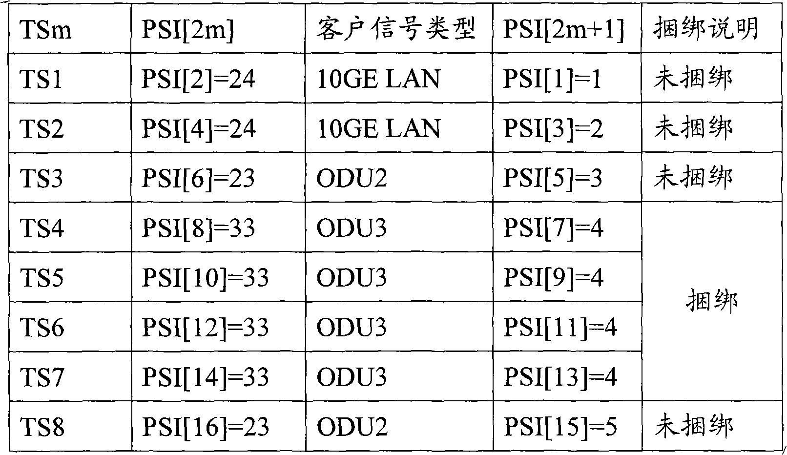
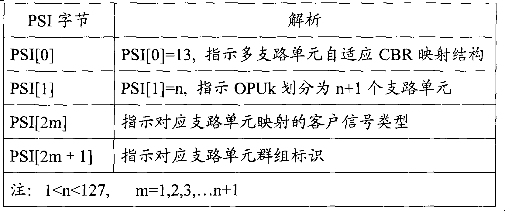
The embodiment of the invention provides a client signal transmission method in an optical transport network and relevant equipment, wherein the embodiment of the method comprises the steps of: obtaining the client signal and mapping the client signal to a tributary unit which is preset in the payload area of the optical-channel payload unit OPUk; respectively marking the corresponding tributary unit of each client signal; marking the tributary unit number of the payload area of the OPUk; marking the type of the mapped client signal in the tributary unit; and sending the optical-channel data unit ODUk including OPUk to the OTN network. The embodiment of the invention is capable of establishing transmission channels suitable for client signal rate, thereby improving the utilization ratio of the transmission channels in the process of the CBR transparent transmission and strengthening the flexible adaptability of the OTN equipment to the access service.
Description
A client signal transmission method and related equipment in an optical transport network technical field The invention relates to optical communication technology, in particular to a mapping transmission method of client signals in an optical transmission network. Background technique With the development of social economy, people's demand for information has increased dramatically. The huge potential bandwidth capacity of optical fiber is about 30THz, making optical fiber communication one of the most important technologies supporting the growth of communication traffic. The optical transport network standard system formulated by the International Telecommunication Union-Telecommunication Standardization Sector (ITU-T, International Telecommunication Union-Telecommunication Standardization Sector) has laid the foundation for building a complete optical transmission basic network. In the Optical Transport Network (OTN, OpticalTransportNetwork), the technology of mapping...
Claims
Login to View More Application Information
Patent Timeline
 Patent Type & Authority Applications(China)
IPC IPC(8): H04B10/12H04L1/00H04L12/56
CPCH04J3/1652H04J3/1658H04J3/1664
Inventor 董立民吴秋游
Owner HUAWEI TECH CO LTD
Features
- R&D
- Intellectual Property
- Life Sciences
- Materials
- Tech Scout
- Unparalleled Data Quality
- Higher Quality Content
- 60% Fewer Hallucinations
Learn More Browse by: Latest US Patents, China's latest patents, Technical Efficacy Thesaurus, Application Domain, Technology Topic, Popular Technical Reports.
© 2025 PatSnap. All rights reserved.Legal|Privacy policy|Modern Slavery Act Transparency Statement|Sitemap|About US| Contact US: help@patsnap.com


