
Automatic transmission and shift control method for said transmission

A technology of automatic transmission and transmission, which is applied in the direction of transmission control, transmission, and components with teeth, etc. It can solve the problems of increasing the difficulty of moving out of the load gear and synchronizing and moving into the target gear, and the impossibility of transmission modification, so as to avoid Delay or acceleration, comfortable running effect

Inactive Publication Date: 2008-10-22
ZF FRIEDRICHSHAFEN AG
View PDF2 Cites 8 Cited by
  • Summary
  • Abstract
  • Description
  • Claims
  • Application Information

AI Technical Summary

Problems solved by technology

The disadvantage of this shifting clutch is that the additional shifting clutch is arranged inside the transmission, since for space reasons a corresponding retrofit to an existing transmission is either completely impossible or would require major modifications
Furthermore, this additional friction clutch configuration requires the engine clutch to remain closed during the shift, which at least increases the difficulty of shifting out of a loaded gear and synchronizing into a target gear

Method used


Image

  • Automatic transmission and shift control method for said transmission
  • Automatic transmission and shift control method for said transmission

Examples


Embodiment Construction

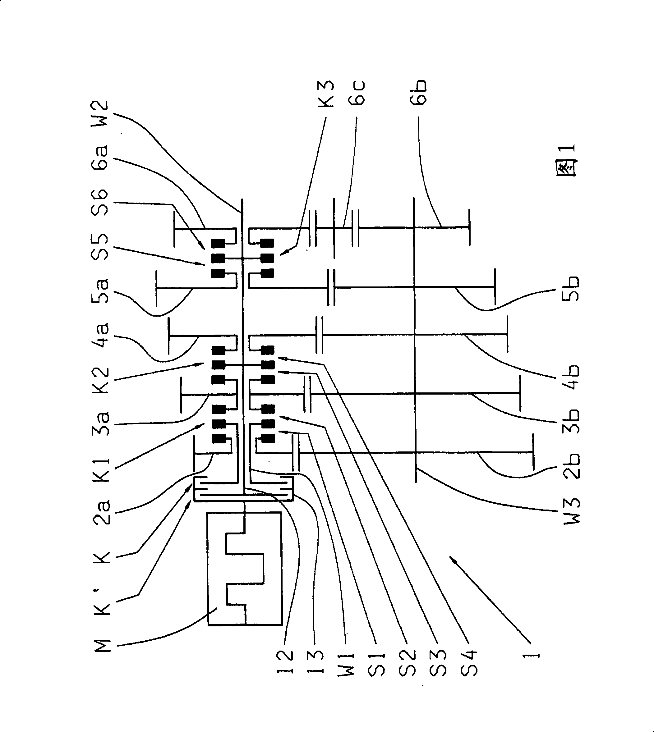
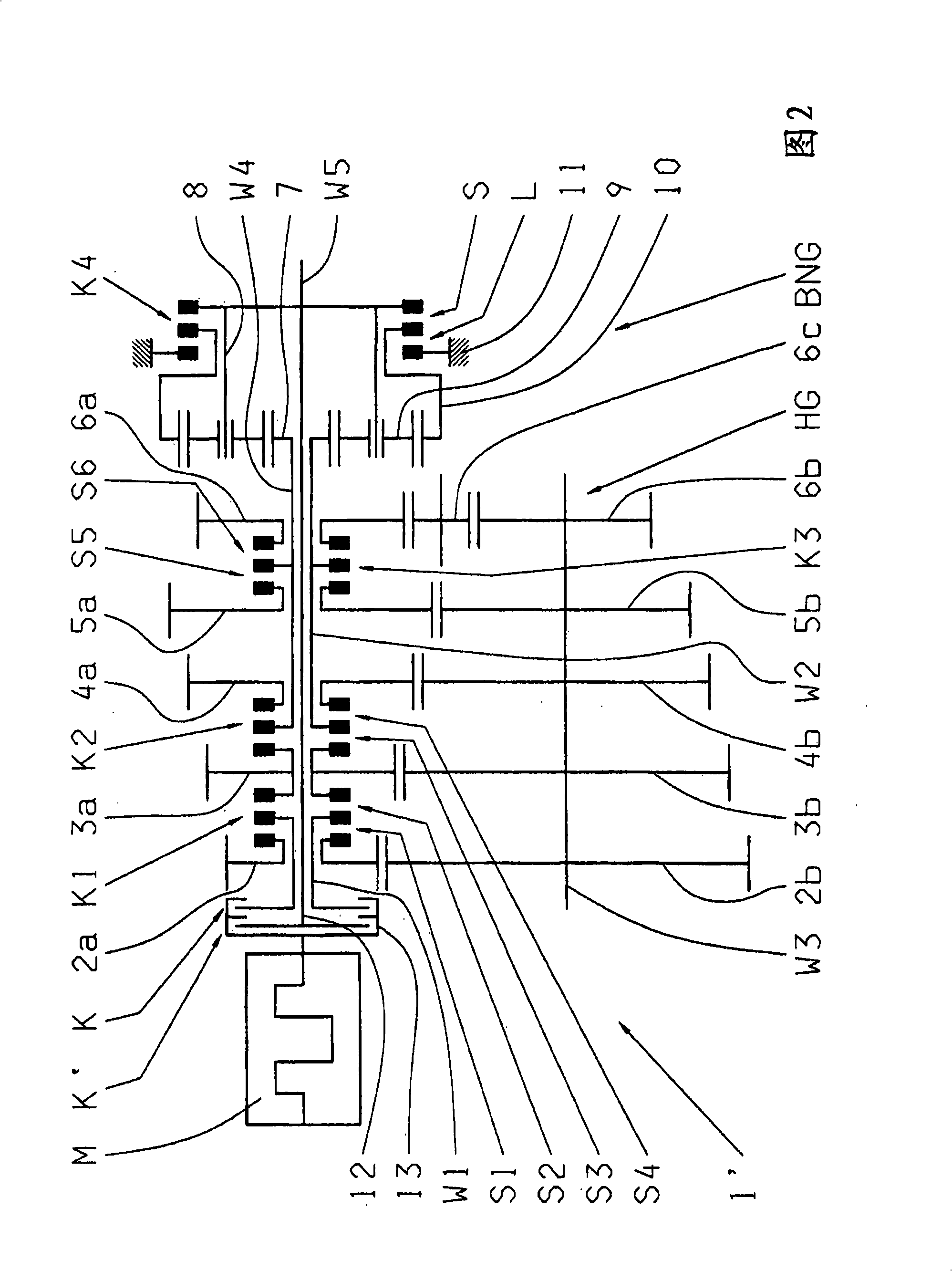
[0026] An automatic transmission 1 as shown in FIG. 1 constitutes a single intermediate shaft transmission, which has an input shaft W1, an output shaft W2 coaxially arranged with the input shaft, and an intermediate shaft W3 arranged parallel to the two transmission shafts W1, W2. An input shaft W1 of the transmission 1 is connected to a drive motor M constituting an internal combustion engine through an engageable and disengageable engine clutch K. The transmission 1 has four selectively shiftable forward gears and one reverse gear.

[0027] In order to shift gears, the input shaft W1 can be connected to the floating wheel 2a of the first gear pair 2a, 2b in the gear position S1 through the first shifting clutch K1 inside the transmission, because the fixed wheel 2b is firmly connected to the intermediate shaft W3 connected, thus establishing a transmission connection between the input shaft W1 and the intermediate shaft W3. Furthermore, as an alternative, the input shaft W...


PUM


Abstract

The invention relates to an automatic transmission of a motor vehicle, comprising an input shaft, an output shaft, arranged coaxially to the input shaft, and a plurality of gears that can be selectively shifted via clutches associated therewith. The input shaft is connected to a driving engine via an engine clutch that can be engaged and disengaged. An additional controlled friction clutch is provided as the powershift clutch for optionally bridging at least one of the clutches. The aim of the invention is to improve a transmission of the aforementioned kind with regard to its performance and for retrofitting an existing transmission. According to the invention, the powershift clutch (K') is effective directly between the driving engine (M) and the output shaft (W2 or W5).; For this purpose, the powershift clutch (K') is arranged on the input end of the clutch (1, 1') in coaxial relation to the engine clutch (K). The gear shafts (W1 or W1, W2, W4) arranged axially between the powershift clutch (K') and the output shaft (W2 or W5) are configured as hollow shafts. The output shaft (W2 or W5) is extended within said gear shafts (W1 or W1, W2, W4) up to the part of the powershift clutch (K') on the transmission end.

Description

technical field [0001] The invention relates to an automatic transmission for automobiles, which has an input shaft, an output shaft arranged coaxially with the input shaft, and a plurality of gears that can be selectively shifted through an associated shifting clutch, wherein the input shaft is engaged and The disengaged engine clutch is connected to the drive motor, and an additional controllable friction clutch is provided as a load shift clutch for bridging at least one of the shift clutches if necessary. [0002] The invention also relates to a method for shift control of an automatic transmission of an automobile having an input shaft, an output shaft arranged coaxially with the input shaft, and a plurality of shifting clutches that can be selectively shifted by corresponding shifting clutches. gear, and wherein the input shaft is connected to the drive motor via an engageable and disengageable engine clutch, wherein during the shifting process, an additional controllabl...

Claims


Application Information

Patent Timeline
Patent Type & Authority Applications(China)
IPC IPC(8): F16H61/04
CPCF16H2061/0407F16H61/04Y10T74/19251F16H3/0915F16H2061/0429F16H2061/0425F16H37/042F16H61/688
Inventor K-F·海因策尔曼
Owner ZF FRIEDRICHSHAFEN AG
Learn More