
Method, device and equipment for vehicle shifting

A gear shifting method and vehicle technology, which is applied in the field of vehicle power systems, can solve the problems of reducing the speed of motors and clutches, high motor speeds, and easy shifting shocks, etc., to achieve the effect of improving ride comfort and realizing the shifting process

Active Publication Date: 2019-07-30
ZHEJIANG GEELY HLDG GRP CO LTD +1
View PDF5 Cites 7 Cited by
  • Summary
  • Abstract
  • Description
  • Claims
  • Application Information

AI Technical Summary

Problems solved by technology

When the vehicle needs to be upshifted during pure electric driving, there are the following problems: (1) The motor speed is too high, the maximum can reach more than 11,000rpm, the speed of the second shaft of the gearbox combined with it and the clutch speed are too high, and the maximum allowable input of the clutch If the rotation speed is around 6500rpm, then it is necessary to consider the hardware protection of the motor and clutch, and reduce the rotation speed of the motor and clutch by upshifting in advance; Restricted coaxial shifting requires a certain shift time, and the upshifting process is prone to shifting shocks

Method used


Image

  • Method, device and equipment for vehicle shifting
  • Method, device and equipment for vehicle shifting
  • Method, device and equipment for vehicle shifting

Examples


Embodiment 1

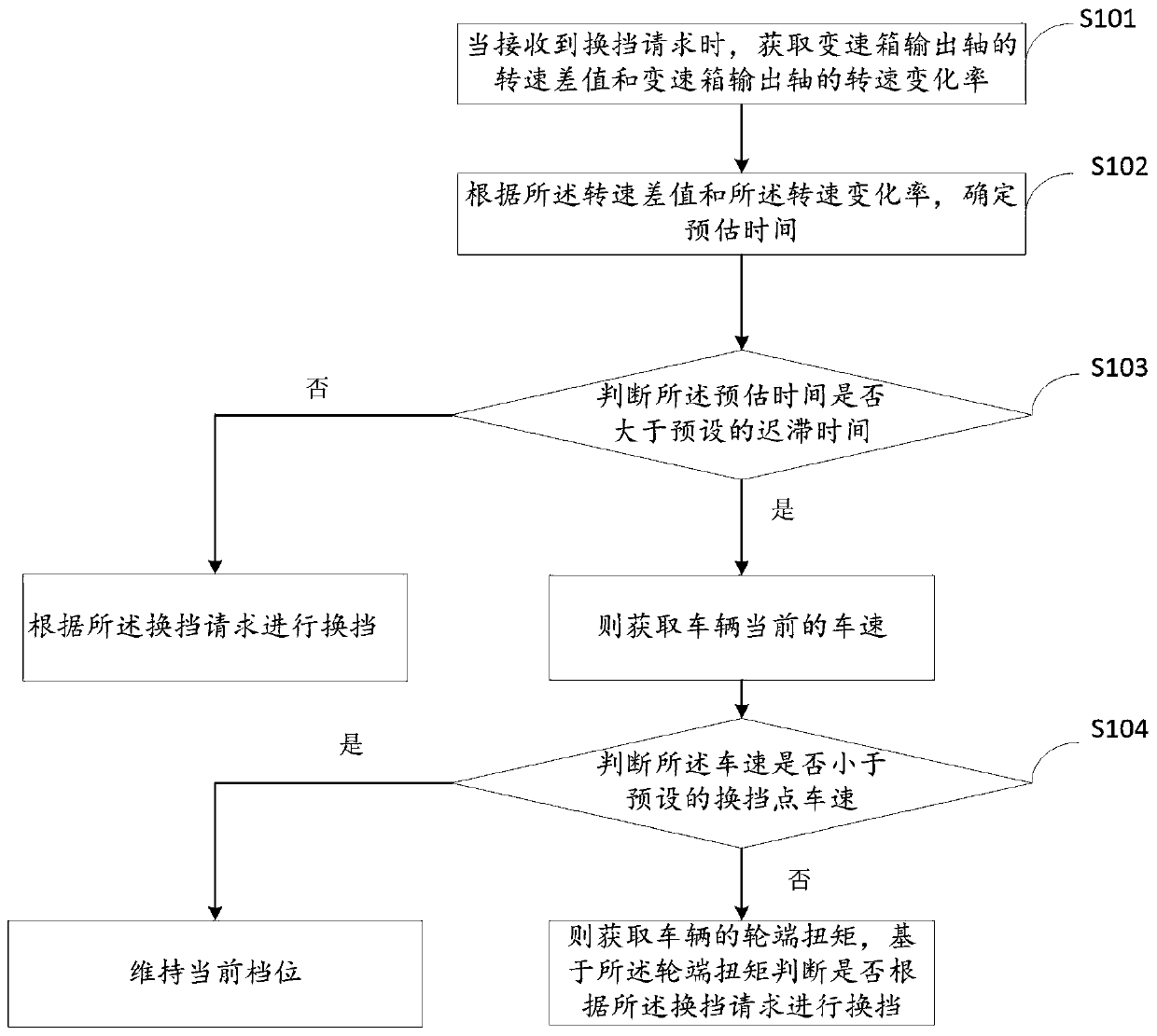
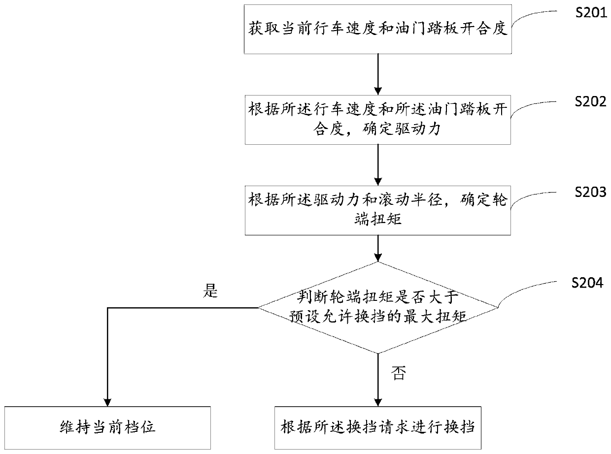
[0064] Embodiment 1 provides a vehicle gear shifting method, combining figure 1 and figure 2 shown, including:

[0065] S101. When a gear shift request is received, acquire the rotational speed difference of the transmission output shaft and the rotational speed change rate of the transmission output shaft.

[0066] Specifically, the rotational speed difference includes:

[0067] Obtain the speed limit value of the gearbox output shaft overdrive and the current speed of the gearbox output shaft;

[0068] Based on the rotational speed limit value and the rotational speed, a rotational speed difference of an output shaft of the gearbox is determined.

[0069] Further, the difference between the rotational speed limit value of the overdrive of the transmission output shaft and the current rotational speed of the transmission output shaft is the rotational speed difference of the transmission output shaft.

[0070] Further, the speed limit value includes:

[0071] Get the cu...

Embodiment 2

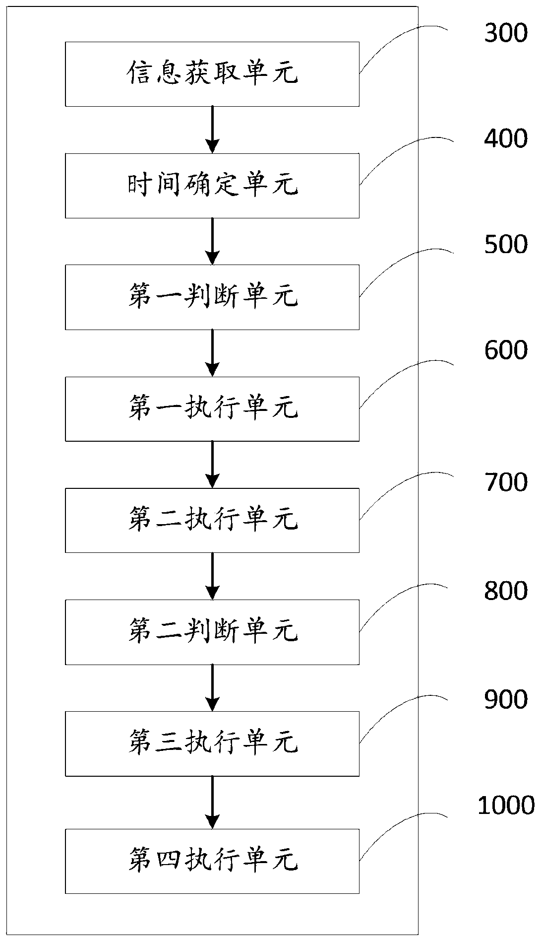
[0101] The second embodiment provides a vehicle gear shifting device, such as image 3 shown, including:

[0102] The information acquiring unit 300 is configured to acquire the rotational speed difference of the transmission output shaft and the rotational speed change rate of the transmission output shaft when a shift request is received;

[0103] A time determination unit 400, configured to determine an estimated time according to the rotational speed difference and the rotational speed change rate;

[0104] A first judging unit 500, configured to judge whether the estimated time is greater than a preset lag time;

[0105] The first execution unit 600 is configured to perform gear shifting according to the gear shift request when the estimated time is not greater than the lag time;

[0106] The second execution unit 700 is configured to acquire the current vehicle speed of the vehicle when the estimated time is greater than the lag time;

[0107] The second judging unit ...

Embodiment 3

[0131] Embodiment 3 provides a vehicle gear shifting device, including: a data acquisition device, a motor controller, a gearbox controller, and a clutch controller;

[0132] The data collection device is used to collect the current vehicle speed and the current motor speed of the vehicle;

[0133] The gearbox controller is used to determine the speed difference of the gearbox output shaft and the speed change rate of the gearbox output shaft;

[0134] The gearbox controller is used to determine the estimated time according to the speed difference of the gearbox output shaft and the speed change rate of the gearbox output shaft;

[0135] The gearbox controller is used to judge whether the estimated time is greater than a preset delay time; if the estimated time is not greater than the delay time, perform gear shifting according to the shift request; If the estimated time is greater than the lag time, then the wheel end torque of the vehicle is obtained, and based on the wheel...


PUM

PropertyMeasurementUnit
Maximum torqueaaaaaaaaaa

Abstract

The invention relates to a method, device and equipment for vehicle shifting. According to the method for vehicle shifting, when a shifting request is received, a rotating speed difference value of agearbox output shaft and a rotating speed change rate of the gearbox output shaft are acquired; estimated time is determined according to the rotating speed difference value and the rotating speed change rate; whether the estimated time is greater than preset lag time is judged; if the estimated time is not greater than the lag time, gear shifting is carried out according to the gear shifting request; if the estimated time is greater than the lag time, a current vehicle speed is acquired; whether the current vehicle speed is smaller than a preset vehicle speed of a gear shifting point is judged; if the current vehicle speed is smaller than the vehicle speed of the gear shifting point, a current gear is maintained; if the vehicle speed is not less than the vehicle speed of the gear shiftingpoint, a vehicle wheel end torque is acquired; and whether to perform gear shifting according to the gear shifting request is judged based on the wheel end torque. According to the method, device andequipment, the lag time is taken as a judgment condition and the wheel end torque is taken as an upshift limit requirement, so that the gear shifting process is completed in advance, and the gear shifting smoothness is improved.

Description

technical field [0001] The invention relates to the technical field of vehicle power systems, in particular to a vehicle gear shifting method, device and equipment. Background technique [0002] With the depletion of traditional energy sources, new energy sources are widely used, especially in the automotive industry. Many large car manufacturers choose hybrid power instead of traditional fuel systems, which can save fuel, reduce energy consumption, and ensure the endurance of the car. [0003] Existing hybrid systems can be driven by an internal combustion engine as the main propulsion device and an electric motor as the auxiliary propulsion device. According to the position of the motor relative to the traditional power system, the single-motor hybrid scheme can be divided into five categories, respectively P0, P1, P2, P3 and P4. [0004] Therein, the electric machine is equipped with at least one energy store, for example an electrochemical energy store for storing elect...

Claims


Application Information

Patent Timeline
IPC IPC(8): F16H61/02F16H59/46F16H59/44F16H59/14
CPCF16H59/14F16H59/44F16H59/46F16H61/0213F16H2059/366
Inventor 吴士朋张天乐陈仁煌崔璐敏梁清华杨培林
Owner ZHEJIANG GEELY HLDG GRP CO LTD
Learn More