Electromagnetic induction heating type electric hair drier

An electromagnetic induction heating and hair dryer technology, applied in induction heating, induction heating devices, applications, etc., can solve problems such as use environment, energy saving, safety noise, etc., achieve uniform flow rate and temperature distribution, strong safety performance, and reduce power consumption Effect

Inactive Publication Date: 2008-10-29
上海超人电气有限公司
View PDF0 Cites 83 Cited by
  • Summary
  • Abstract
  • Description
  • Claims
  • Application Information

AI Technical Summary

Problems solved by technology

[0009] In view of the above, the technical problem to be solved and the technical task proposed by the present invention are to overcome the existing problems and defects in the use environment, ener

Method used


Image

  • Electromagnetic induction heating type electric hair drier
  • Electromagnetic induction heating type electric hair drier
  • Electromagnetic induction heating type electric hair drier

Examples


Embodiment 1

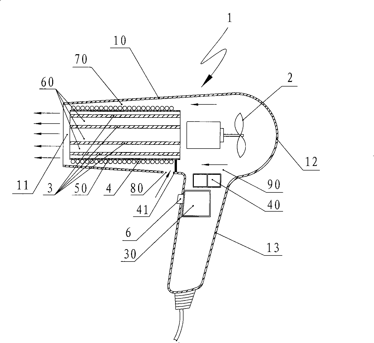
[0041] Such as Figure 1A with Figure 1B As shown, the hair dryer 1 of the present embodiment mainly includes a tubular hollow main casing 10, one end of which has an airflow inlet 12, and the opposite end has an airflow outlet 11, and a handle casing 13 with a switch 6 is formed from the hollow main casing 10. It extends downward and is integrated with the hollow main casing 10 , and the upper end 90 of the handle casing 13 is an open surface.

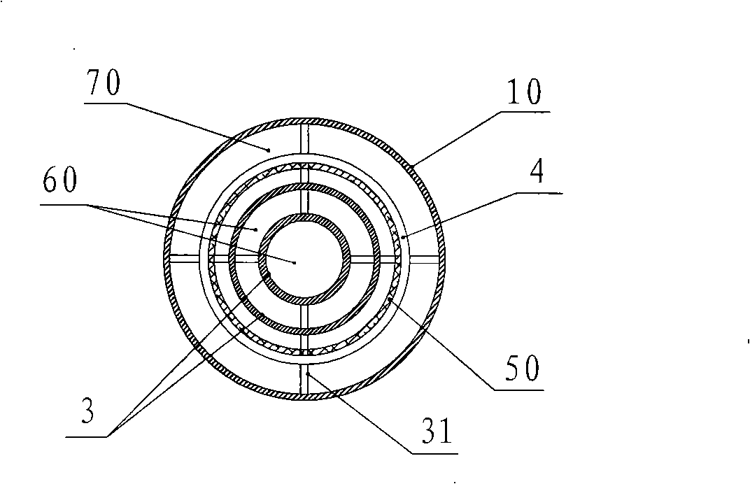
[0042] In the main housing 10, the fan 2 is disposed between the air inlet 12 and the air outlet 11, and defines a pair of first air flow passage 60 and second air flow passage 70, the first air flow passage 60 and the second air flow passage 70 Extending toward the air outlet 11 , the first air flow channel 60 and the second air flow channel 70 are separated from each other by a tubular partition wall 50 . In the present embodiment, the tubular partition wall 50 is formed by a cylindrical tube made of mica sheet, which is arranged...

Embodiment 2

[0048] Except for the following features, the hair dryer of this embodiment is basically the same as the hair dryer of Embodiment 1. Therefore, repeated explanations are omitted.

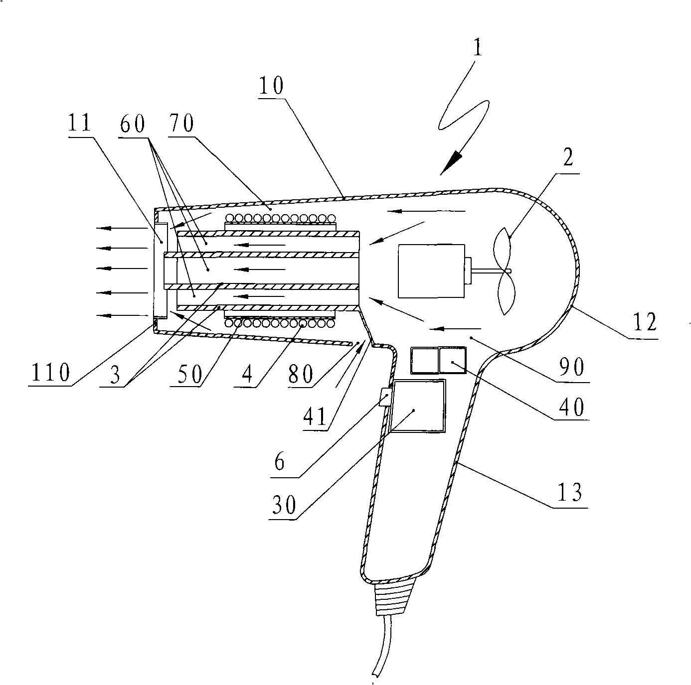
[0049] In this example, if figure 2 As shown, the cylindrical thin-walled tube as the heat generating part 3 in the first airflow passage 60 extends further to the airflow outlet of the hair dryer 1 than the tubular partition wall 50 as the partition wall between the first airflow passage 60 and the second airflow passage 70 11, and an annular retaining ring 110 is added on the airflow outlet 11 section to prevent the airflow from the second airflow passage 70 from directly jetting out of the airflow outlet 11, so that the electromagnetic coil 4 is carried out through the second airflow passage 70 After the cooled air flow comes out from the second air flow channel 70 , it first merges into the first air flow channel 60 , and then sprays out from the air flow outlet 11 of the hair dryer 1 . There...


PUM


Abstract

The invention discloses an electromagnetic induction heating electric hair dryer, pertaining to an airflow generation and heating device. The electrical-heating hair dryer in the prior art has problems and defects in the aspects of application environment, energy saving, safety, noise, comfort, etc. A heater of the hair dryer of the invention comprises an electromagnetic induction eddy-flow heating component served as a heat generation component, electromagnetic coils winding outside the heat generation component and an electronic control circuit that is electrically connected with the electromagnetic coils and positioned outside an airflow channel. As the electric hair dryer adopts the electromagnetic induction to heat air, compared with the hair dryer with electrical heating in the prior art, the heating efficiency of the hair dryer of the invention is greatly improved and the heated air can smoothly flow in the airflow channel, thus the power consumption and operating noise of the hair dryer are remarkably reduced; the flowing speed of the airflow and the temperature distribution at the outlet section of the electric hair dryer are more even and the hair dryer is safer and more comfortable and can save more electricity when in use.

Description

technical field [0001] The invention belongs to an airflow generating and heating device, in particular to a hair dryer which adopts electromagnetic induction heating method to heat the flowing airflow. Background technique [0002] Existing hair dryer 1A such as image 3 As shown, it is a hair dryer that uses resistance heating to heat the air flowing through it, and it includes: [0003] a main housing 10A having an air inlet 12A and an air outlet 11A; [0004] a fan 2A disposed between said air inlet 12A and said air outlet 11A in said main housing 10A; [0005] an air flow passage 60A, located downstream of the fan 2A, extending toward the air outlet 11A in the main housing 10A; [0006] An electric heater 3A arranged in the airflow channel 60A, the electric heater 3A is formed by a resistance wire 4A wound in a helical form on a central support 31A made of a mica sheet. [0007] The hair dryer with the above structure uses resistance heating to heat the air flowing t...

Claims


Application Information

Patent Timeline
IPC IPC(8): A45D20/10A45D20/12H05B6/14
Inventor 应平祥
Owner 上海超人电气有限公司
Why Eureka
Try Eureka