Chemical water pump

A water pump and chemical technology, which is applied in the field of centrifugal chemical water pumps, can solve the problems of high energy consumption, the pump shaft is easily corroded by chemical liquid, and the centrifugal chemical water pump cannot achieve reasonable pressure and flow, so as to achieve the effect of preventing corrosion

Inactive Publication Date: 2008-10-29
杨军 +1
View PDF0 Cites 2 Cited by
  • Summary
  • Abstract
  • Description
  • Claims
  • Application Information

AI Technical Summary

Problems solved by technology

[0003] The technical problem to be solved by the present invention is: to overcome the problems that the existing centrifugal chemical water pumps cannot achieve reasonable pressure and flow, consume large energy, and the pump shaft is easily corroded by chemical liquid, and provide a pump that can achieve reasonable pressure and flow, and can Centrifugal chemical water pump with low power consumption and effective protection of the pump shaft from corrosion

Method used


Image

  • Chemical water pump
  • Chemical water pump
  • Chemical water pump

Examples


Embodiment Construction

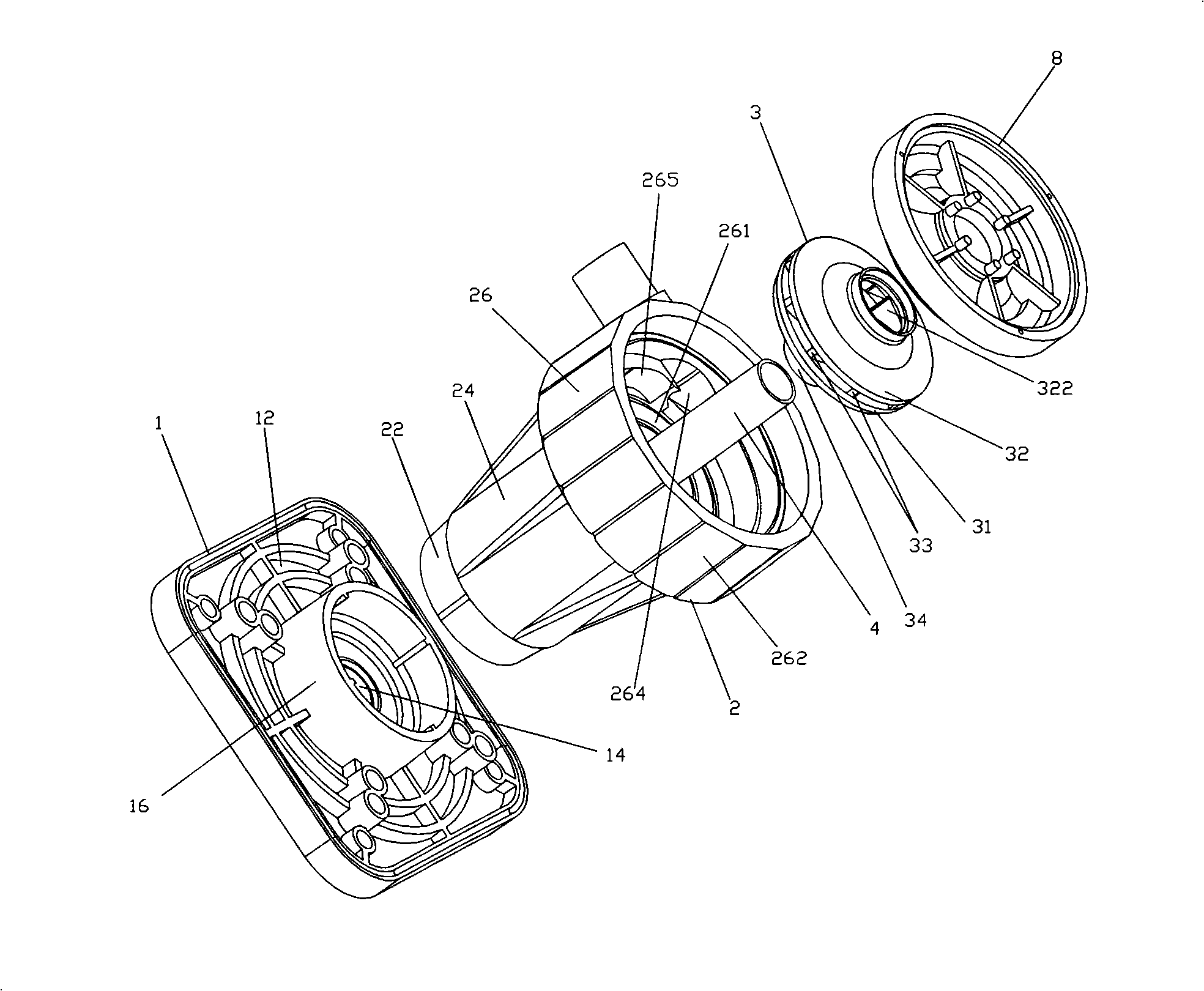
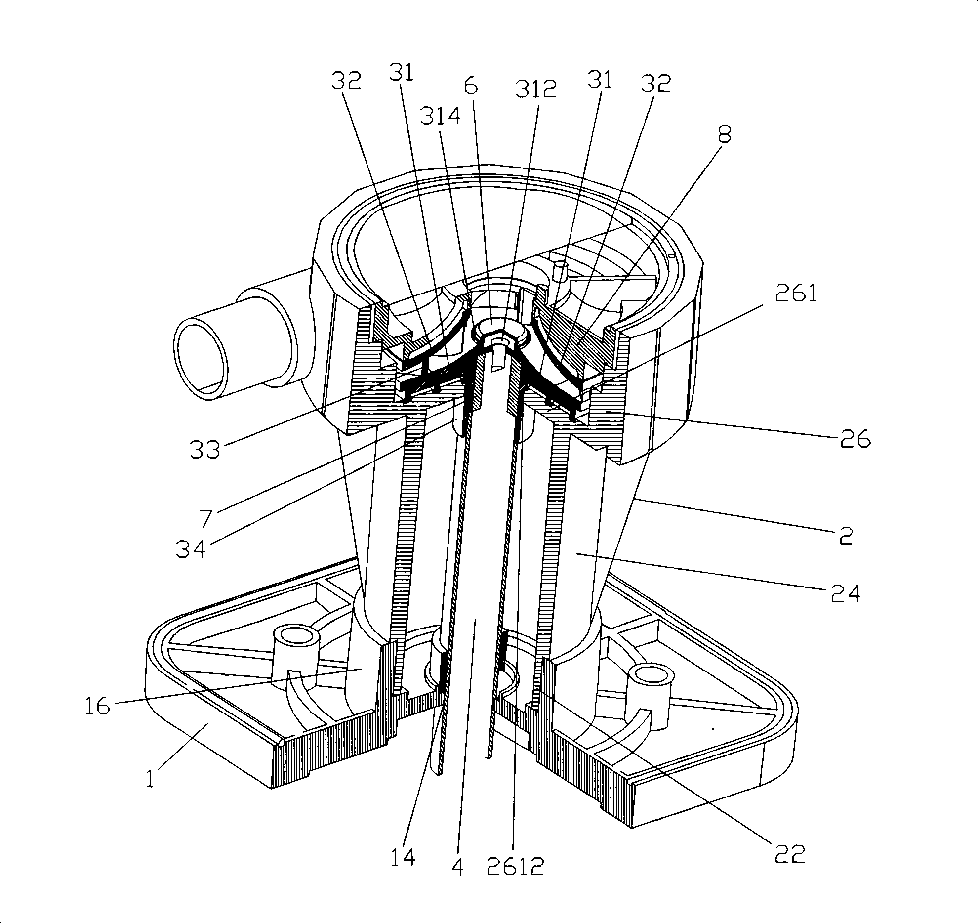
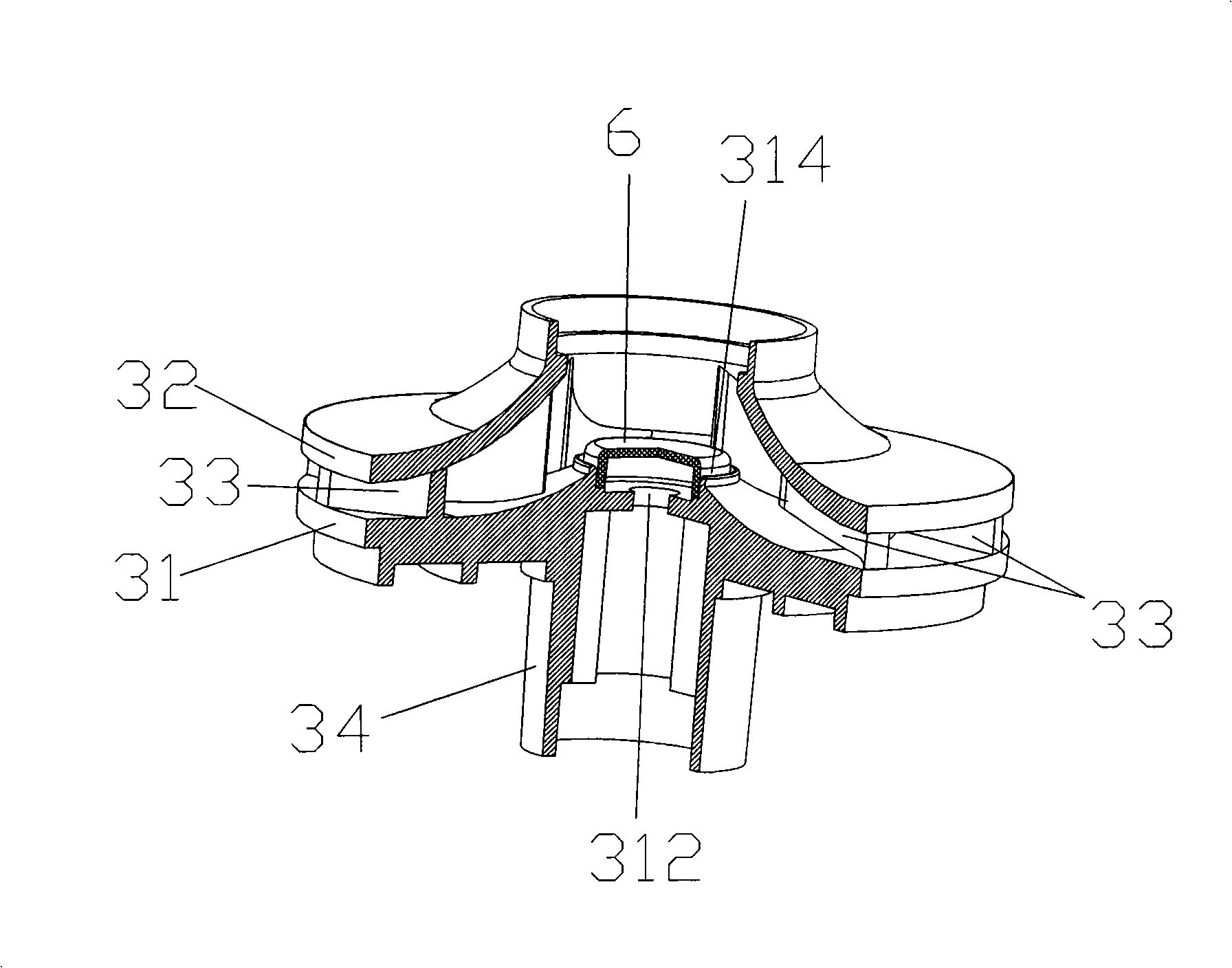
[0022] see Figure 1 to Figure 4 , a centrifugal chemical water pump, which includes a base 1, a pump body 2, an impeller 3, a pump shaft 4, a screw (not shown), a sealing cap 6, a sealing ring 7, a pump cover 8.

[0023] The base 1 includes a bottom plate 12 , a first through hole 14 , and a sleeve 16 . The first through hole 14 is defined in the middle of the bottom plate 12 . The sleeve 16 surrounds the first through hole 14 and protrudes outside the first through hole 14 .

[0024] The pump body 2 includes an annular lower shell 22 , a middle shell 24 , and an upper shell 26 .

[0025] The lower case 22 is inserted into the bushing 16 .

[0026] The middle shell 24 is connected between the lower shell 22 and the upper shell 26 .

[0027] The upper shell 26 includes a bottom plate 261 , an annular sidewall 262 , a water inlet (not labeled), a water outlet 264 , and a rib 265 .

[0028] A second through hole 2612 is defined in the center of the bottom plate 261 .

[00...


PUM


Abstract

The invention relates to a centrifugal chemical pump which comprises a pump body, an impeller and a pump shaft driving the impeller to rotate; wherein the pump body comprises an upper shell; the upper shell comprises a bottom plate, a ring-shaped lateral wall, a water inlet, a water outlet and a cog; the lateral wall is arranged on the edge of the bottom plate in a winding manner, the water inlet is arranged at the top end of the upper shell, the water outlet is arranged in the position of the lateral wall near the bottom plate, the cog is involute-structured, namely, the cog is arranged in the intersection position of the bottom plate and the lateral wall in a winding manner, both ends of the cog are respectively arranged at the both ends of the water outlet, and the thickness of the cog gradually turns smaller; the impeller arranged on the upper shell of the pump body comprises a rib wheel, a cover wheel and a plurality of main blades; wherein, the cover wheel is arranged above the rib wheel in an overlapping manner, the arc-shaped main blades are arranged between the rib wheel and the cover wheel. The centrifugal chemical pump can achieve reasonable pressure and flow rate, ensure low energy consumption and effectively prevent the pump shaft from being corroded.

Description

technical field [0001] The invention relates to a centrifugal chemical water pump, in particular to a centrifugal chemical water pump capable of achieving reasonable pressure and flow, low energy consumption and effectively protecting the pump shaft from corrosion. Background technique [0002] Centrifugal pumps are general-purpose machinery in industry and are widely used in various fields of the national economy. The impeller of the existing centrifugal pump imitates the hydraulic model. It is difficult to find the best parameters by this method, so it cannot achieve reasonable pressure and flow, and the energy consumption is also large. In addition, the pump shaft is not effectively isolated and protected, so it is easy to be separated from the Corroded by contact with chemical fluids. Contents of the invention [0003] The technical problem to be solved by the present invention is: to overcome the problems that the existing centrifugal chemical water pumps cannot achi...

Claims


Application Information

Patent Timeline
Patent Type & Authority Applications(China)
IPC IPC(8): F04D7/02F04D29/42F04D29/24F04D29/12
Inventor 杨军陈文忠
Owner 杨军
Why Eureka
Try Eureka