
Method for dynamically measuring interference signal analysis

A dynamic interference and interference signal technology, applied in the field of interference signal analysis, can solve problems such as the inability to effectively use the high-frequency vibration of the object to be tested, the pulse time δT limit, and the precise position that is not easy to compare the maximum interference intensity.

Active Publication Date: 2010-11-17
IND TECH RES INST
View PDF5 Cites 0 Cited by
  • Summary
  • Abstract
  • Description
  • Claims
  • Application Information

AI Technical Summary

Problems solved by technology

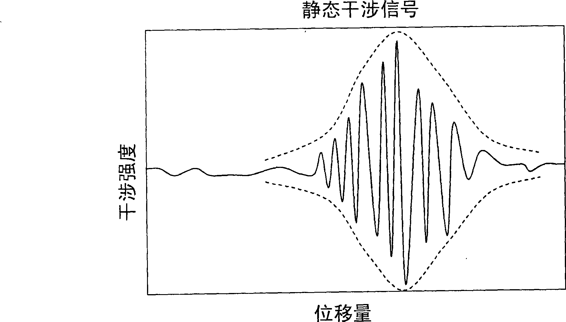
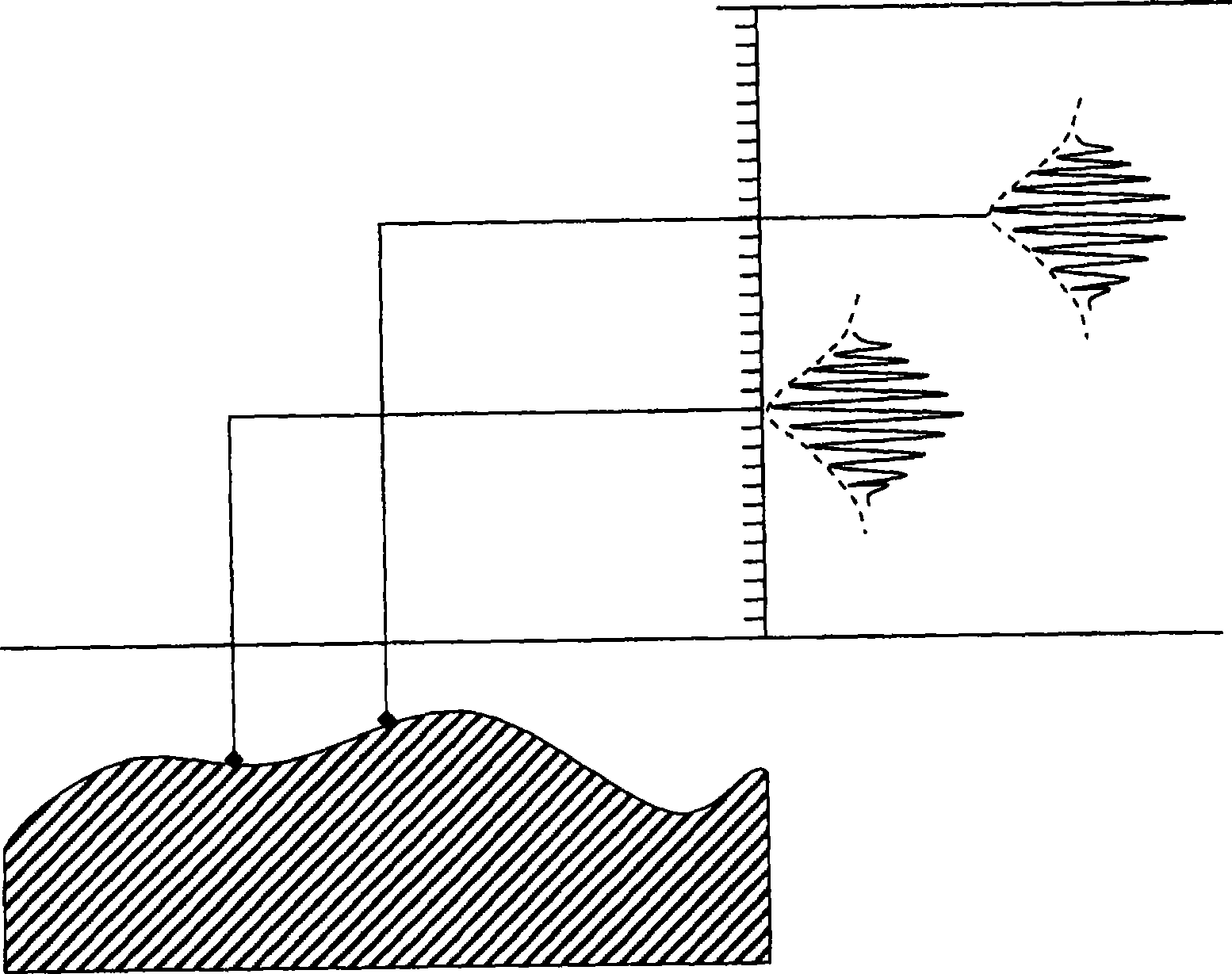
This will make it difficult to calculate the precise position of the maximum interference intensity contrast of the dynamic interference signal, and thus cannot accurately reconstruct the three-dimensional profile of the object to be measured 50
[0017] Although reducing the pulse time δT of the stroboscopic pulse beam 312 can improve the interference contrast of the dynamic interference signal, however, because the stroboscopic pulse beam 312 is not a mathematically ideal Delta function, the pulse time δT still has a physical limit
As a result, the known method of dynamically measuring the surface profile of the object under test cannot be effectively applied to the situation where the object under test vibrates at a high frequency

Method used


Image

  • Method for dynamically measuring interference signal analysis
  • Method for dynamically measuring interference signal analysis
  • Method for dynamically measuring interference signal analysis

Examples


Embodiment Construction

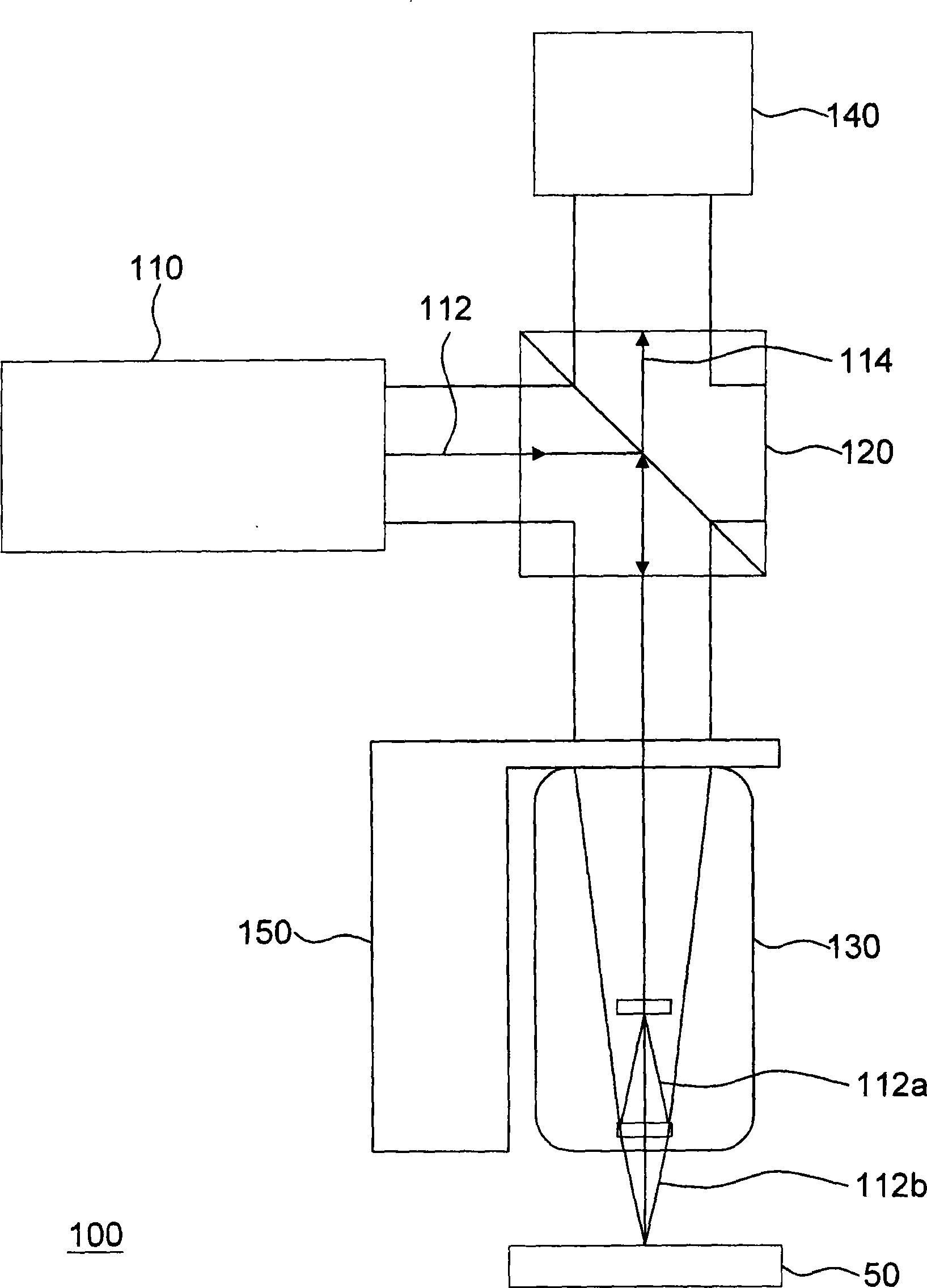
[0038] Figure 5 It is a flowchart of a method for analyzing a dynamic measurement interference signal according to an embodiment of the present invention, and the measurement structure used in the method for analyzing a dynamic measurement interference signal of the present invention can be as follows image 3 dynamic measuring mechanism. Please refer to Figure 5 and image 3 , the method for analyzing the dynamic measurement interference signal of the present invention includes the following steps: when the object to be measured 50 vibrates, capture the dynamic interference signal S51, wherein the intensity of the interference beam 314 changes due to the different optical path differences of the sequence, which is the dynamic interference Signal. The process of extracting the dynamic interference signal has been described in detail above, and will not be repeated here.

[0039] When the object under test 50 vibrates at high frequency, the interference contrast of the dy...


PUM


Abstract

A method of resolving interference signals of dynamic measurement is provided, and is suitable for measuring dynamic characteristics of a unit to be measured. The method includes the following steps: capturing the dynamic interference signals when the unit to be measured vibrates; and carrying out deconvolution operation on the dynamic interference signals so as to acquire the reduced dynamic interference signals.

Description

technical field [0001] The present invention relates to a method for analyzing interference signals, and in particular to a method for analyzing dynamic measurement interference signals. Background technique [0002] The traditional optical interference surface topography micrometer is mainly used to measure the size of the three-axis undulation of the microstructure surface. Measurement, measurement of laser marking depth, measurement of the size and coplanarity of gold ball bumps in the flip-chip process, measurement of the size and height of the spacer on the new color filter in the liquid crystal flat panel display, Measurement of fiber end faces and surface topography of micro-optical components, etc. In recent years, some people have added the function of dynamic measurement, and expanded the application field of this type of measuring instrument to cover the observation and measurement of dynamic behavior of functional components and thin films in the micro-mechanica...

Claims


Application Information

Patent Timeline
Patent Type & Authority Patents(China)
IPC IPC(8): G01B9/023
Inventor 陈亮嘉张中柱黄耀庭陈金亮
Owner IND TECH RES INST
Learn More