

Film sensor calibration device and method
A thin-film sensor and calibration device technology, which is applied in the field of sensor calibration, can solve problems such as the inability to accurately obtain the dynamic characteristics of the thin-film sensor, the inability to accurately determine the load value of the thin-film sensor, etc., and achieve the effect of convenient control, accurate acquisition, and control of the heating range
- Summary
- Abstract
- Description
- Claims
- Application Information
AI Technical Summary
Problems solved by technology
Method used
Image


Examples
Embodiment 1
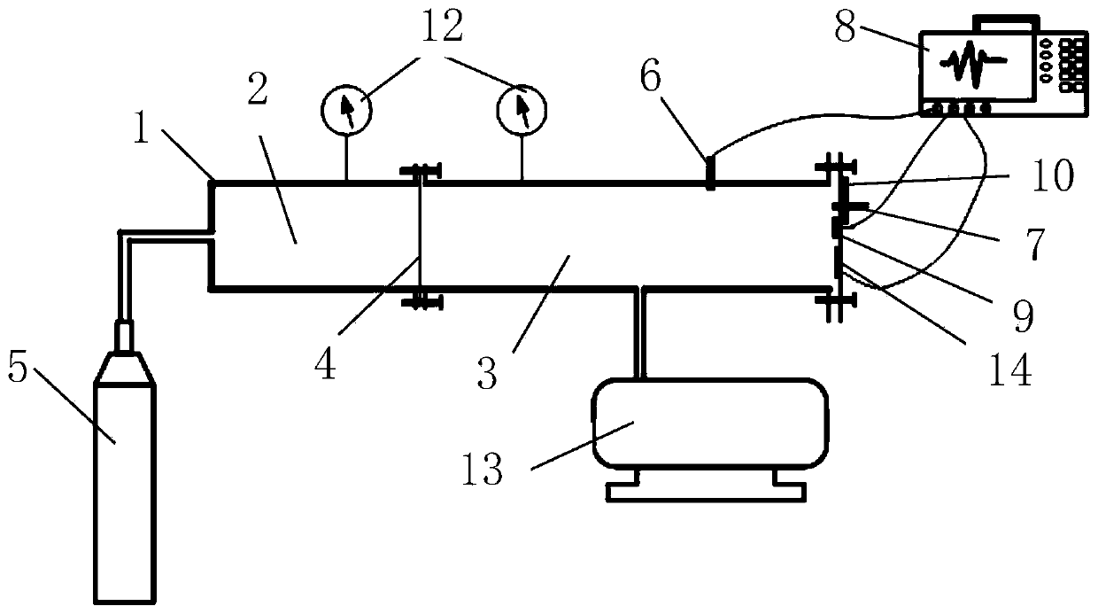
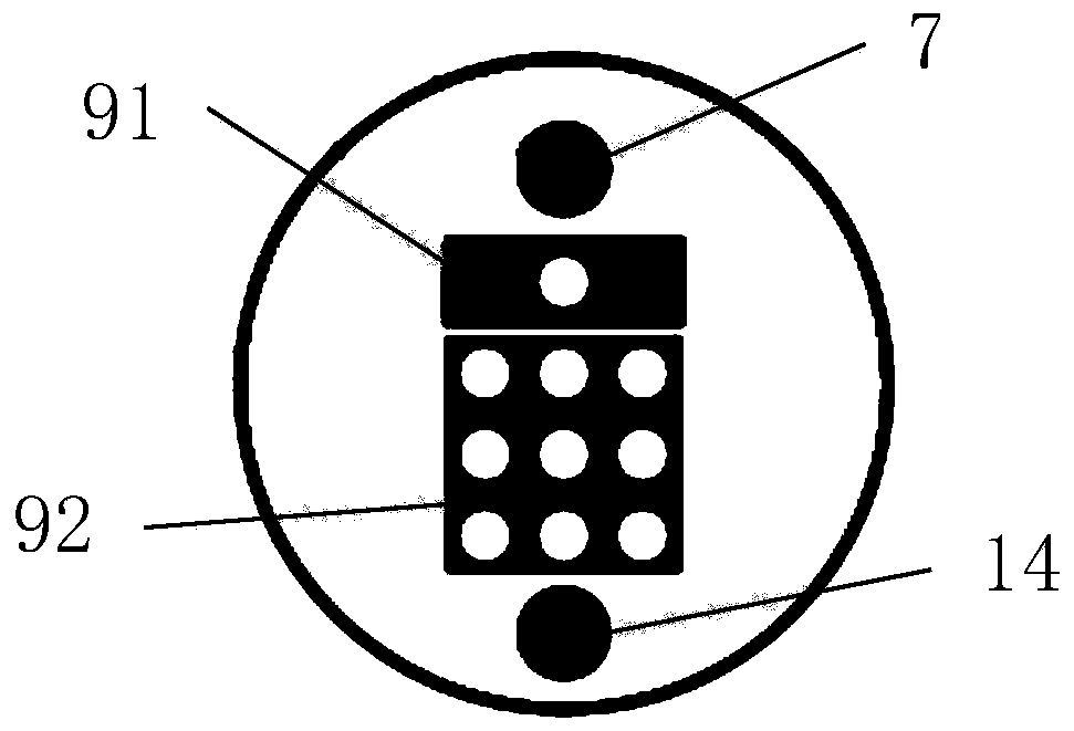
[0051] The present invention provides a calibration device for a thin film sensor 9, comprising a shock tube 1, an air supply device 5, a first pressure sensor 6, a second standard pressure sensor 7, and an oscilloscope 8, using the shock wave generated by the shock tube 1 as an excitation source , using the comparison method to obtain the dynamic characteristic parameters of the thin film sensor 9, by using the first pressure sensor 6 as the trigger signal source of the oscilloscope 8 to accurately capture the electrical signal of the thin film sensor 9 and the rising edge signal of the second standard pressure sensor 7, so that The dynamic characteristics of the thin film sensor 9 can be accurately obtained, and the calibration of the dynamic characteristics of the thin film sensor 9 including a single measuring point and a multi-measuring point array can be realized.
[0052] see Figures 1 to 3, the shock tube 1 includes a connected high-pressure pipe body 2 and a low-pres...
Embodiment 2
[0055] The present invention provides a thin film sensor 9 calibration method, based on the above thin film sensor 9 calibration device, specifically comprising the following steps:
[0056] Step1: Turn on the air supply device 5 to inflate the high-pressure pipe body 2 until the diaphragm 4 ruptures to generate a shock wave;
[0057] Specifically, before this step, the diaphragm 4 should be installed between the shock tube 1, the high-pressure pipe body 2 and the low-pressure pipe body 3, and the thin film sensor 9 to be calibrated, the second standard pressure sensor 7, and the temperature sensor 14 should be flattened. Install it on the test end face, install the first pressure sensor 6 on the inner wall of the low-pressure pipe body 3 at a distance of 1m in front of the test end face; paste the semiconductor refrigeration chip 10 on the outer end face opposite to the test end face with silicone grease, and install the fan with Silicone grease is pasted on the semiconductor...
Embodiment 3
[0066] The present invention provides a method for calibrating a thin film sensor 9, and the above-mentioned thin film sensor calibrating device comprises the following steps:
[0067] Step1: Open the air supply device 5 to inflate the high-pressure pipe body 2 until the diaphragm 4 ruptures to generate a shock wave;
[0068] Specifically, before this step, the diaphragm 4 should be installed between the shock tube 1, the high-pressure pipe body 2 and the low-pressure pipe body 3, and the thin film sensor 9 to be calibrated, the second standard pressure sensor 7, and the temperature sensor 14 should be flattened. Install it on the test end face, install the first pressure sensor 6 on the inner wall of the low-pressure pipe body 3 at a distance of 1m in front of the test end face; paste the semiconductor refrigeration chip 10 on the outer end face opposite to the test end face with silicone grease, and install the fan with Silicone grease is pasted on the semiconductor refriger...
PUM
 Abstract
Description
Claims
Application Information