

Back light source structure
A backlight and microstructure technology, applied in light guides, optics, optical components, etc., can solve the problems of optical film light guide plate deformation, not very wide range of use, high price, etc., and achieve the effect of improving luminous efficiency
- Summary
- Abstract
- Description
- Claims
- Application Information
AI Technical Summary
Problems solved by technology
Method used
Image

Examples
Embodiment 1
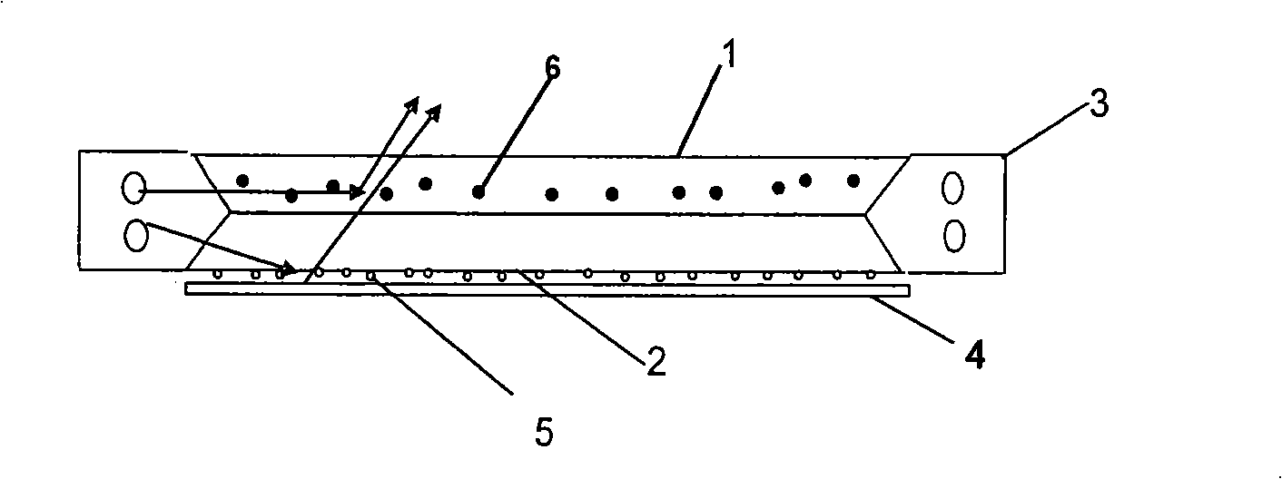
[0019] figure 2 Shown is a specific embodiment of the backlight structure and the light guide plate of the present invention. Such as figure 2 As shown, the backlight structure in this embodiment includes a lamp reflector 3, two light guide plates (upper light guide plate 1 and lower light guide plate 2), a bottom reflection film 4 and other optical films (not shown in the figure) . Wherein, the lower surface of the lower light guide plate 2 has concave or convex microstructures 5, which are used as the lower surface of the light guide plate and are opposite to the bottom reflective film 4 . There are no microstructures on the upper and lower surfaces of the upper light guide plate 1 , but some polymer particles that diffuse light are dispersed inside. The upper surface of the upper light guide plate 1 is the light emitting surface.
[0020] In this embodiment, since the scattering particles 6 in the upper light guide plate 1 can directly change the propagation direction...
Embodiment 2
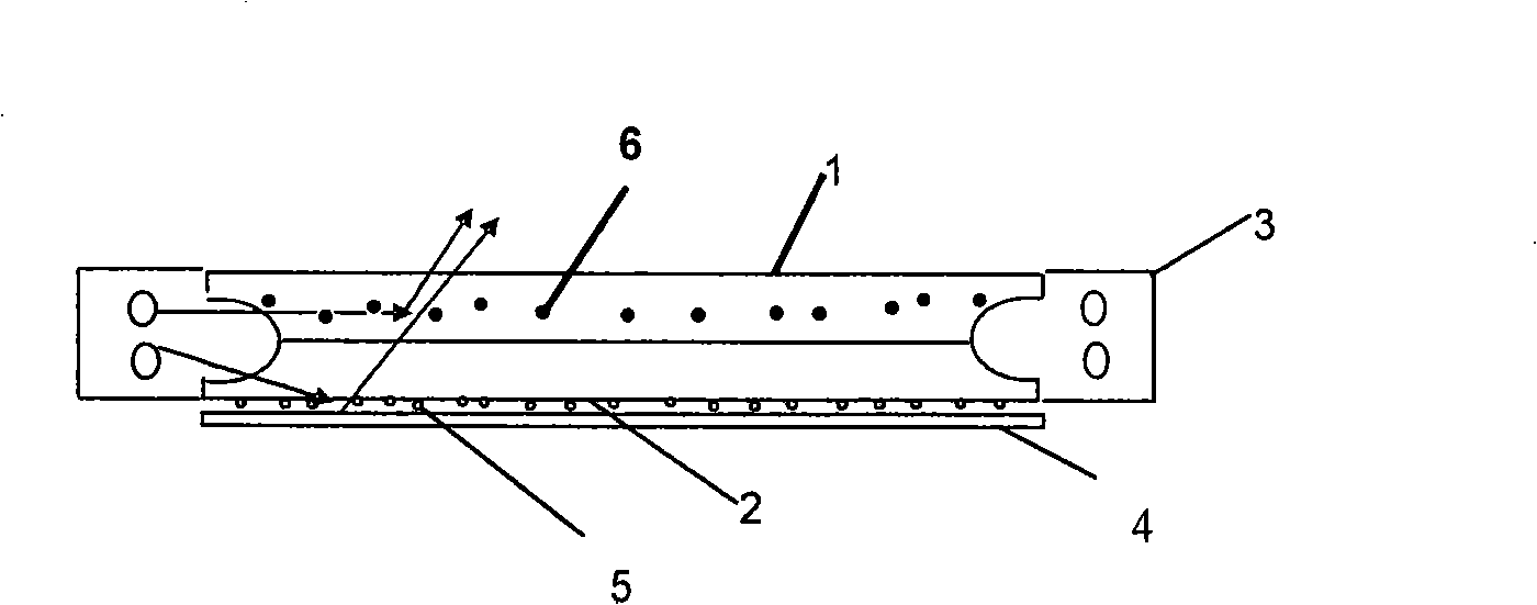
[0025] image 3 Shown is the second embodiment of the backlight structure and the light guide plate of the present invention. Such as image 3 As shown, the structure of the light guide plate in this embodiment is roughly the same as that of the specific embodiment 1, and the difference between the specific embodiment 1 lies in the structure formed on the light incident surface of the upper layer light guide plate 1 and the lower layer light guide plate 2. In this embodiment, the upper layer The light guide plate 1 and the lower light guide plate 2 both form a concave arc surface near the light entrance of the lamp chamber 3, and the arc surfaces of the upper and lower light guide plates are symmetrical, so that the two light guide plates will form a "U" shaped structure. The functions and effects of each part of the backlight structure in this embodiment are the same as those in the first embodiment.
Embodiment 3
[0027] image 3 Shown is the third embodiment of the backlight structure and the light guide plate of the present invention. Such as image 3 As shown, the structure of the light guide plate in this embodiment is roughly the same as that of the specific embodiment 1, and the difference between the specific embodiment 1 lies in the structure formed on the light incident surface of the upper layer light guide plate 1 and the lower layer light guide plate 2. In this embodiment, the upper layer The light guide plate 1 and the lower light guide plate 2 both form a concave 1 / 4 arc surface near the light incident place of the lamp chamber 3, so that the two light guide plates will form a semicircular light incident surface. The functions and effects of each part of the backlight structure in this embodiment are the same as those in the first embodiment.
[0028] The light-incident surfaces in the above-mentioned embodiments can also be modified in various forms, such as irregular c...
PUM
 Abstract
Description
Claims
Application Information