Electric connector and manufacturing method thereof

A technology of an electrical connector and a manufacturing method, which is applied in the field of electrical connectors and its manufacturing, can solve the problems of complex production processes, immovable solder balls, scratches, etc., and achieve the effects of reducing production processes, simple processing, and avoiding scratches

Active Publication Date: 2008-10-29
DEYI PRECISION ELECTRONIC IND CO LTD PANYU
View PDF0 Cites 4 Cited by
  • Summary
  • Abstract
  • Description
  • Claims
  • Application Information

AI Technical Summary

Problems solved by technology

[0002] At present, the known electrical connector includes an insulating body provided with a plurality of terminal receiving grooves, a plurality of terminals and solder balls, and the terminals can hold the solder balls, but the solder balls of this electrical connector cannot Therefore, it may cause uneven docking between the electrical connector and the circuit board, and an electrical connector disclosed in Taiwan Patent No. 094123035, the electrical connection includes an insulating base body with a plurality of terminal slots and

Method used


Image

  • Electric connector and manufacturing method thereof
  • Electric connector and manufacturing method thereof
  • Electric connector and manufacturing method thereof

Examples


Example Embodiment

[0023] The electrical connector of the present invention will be further described below in conjunction with the accompanying drawings.
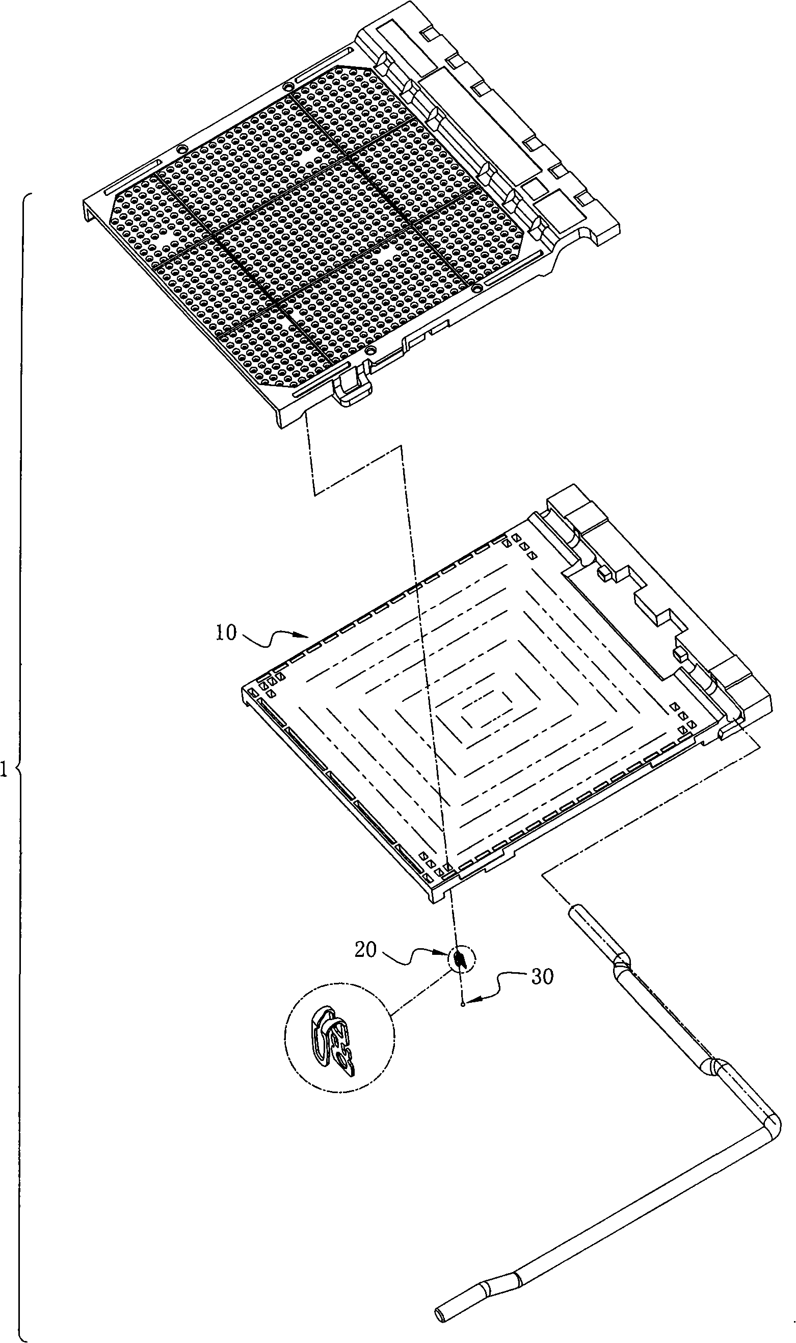
[0024] The electrical connector 1 of the present invention, see figure 1 , Including an insulating body 10 and a plurality of conductive terminals 20 and solder balls 30. The lower end is connected to the circuit board 2, and the upper end is connected to the central processing unit 3, such as Figure 14 .

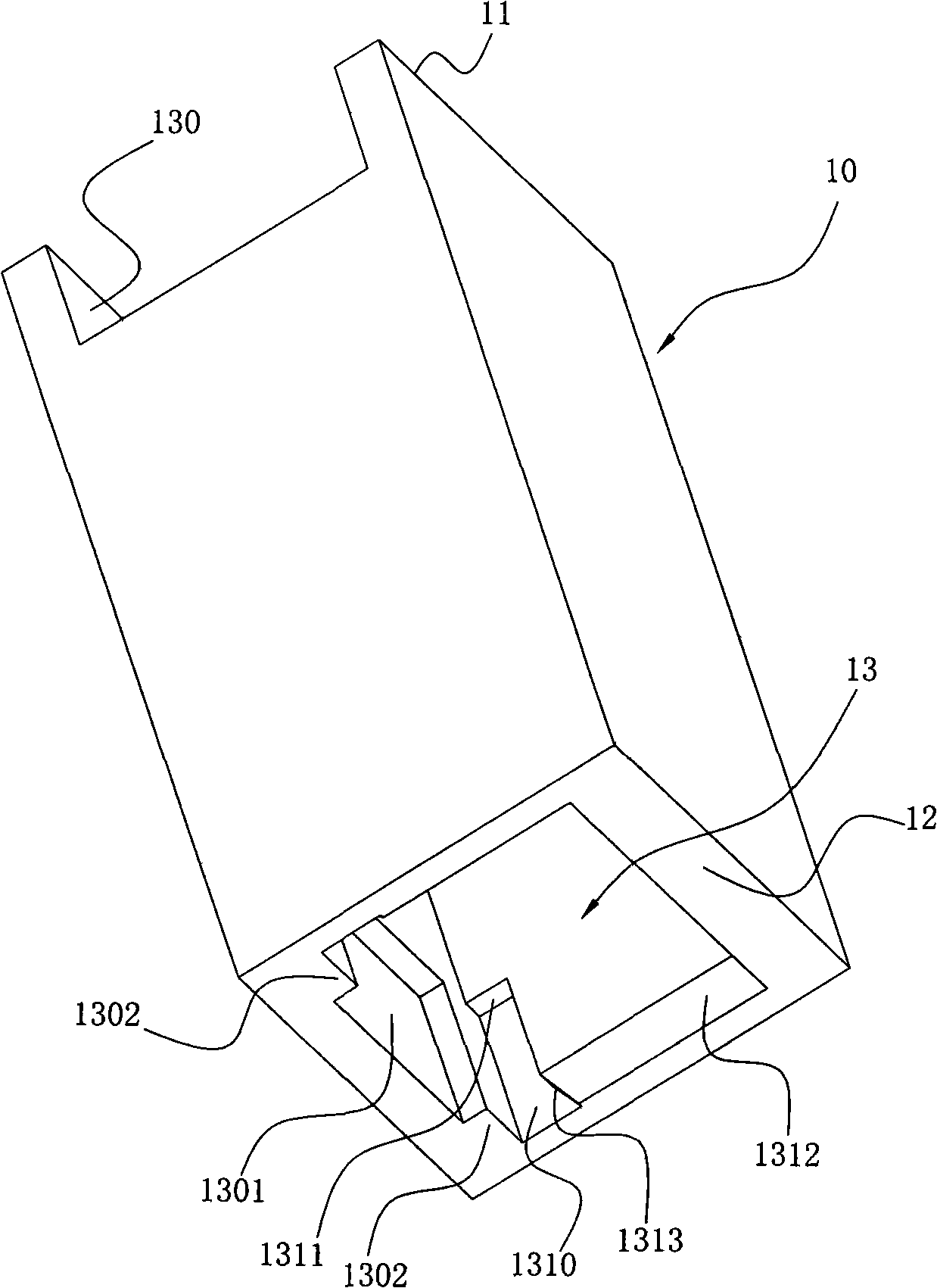
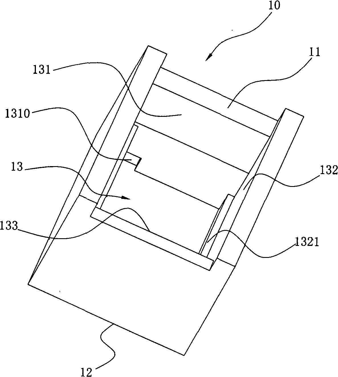
[0025] Please refer to Figure 2 to Figure 3 , The insulating body 10 is provided with an upper surface 11 and a lower surface 12, and a plurality of receiving holes 13 penetrate the upper and lower surfaces 11, 12 ( figure 2 , 3 Only one of them is shown), the receiving hole 13 is provided with a first inner side wall 130, opposite to the first inner side wall is a third inner side wall 132, and the other two inner side walls are respectively a second inner side wall 131 and a fourth inner side wall The walls 133 are arranged in a clockwis...


PUM


Abstract

The invention relates to an electric connector which comprises an insulation body provided with a plurality of holding holes, and a plurality of terminals and solder balls held in the holding holes; the terminals are provided with via holes; the solder balls are held in the via holes; the edge of the via hole is provided with a round corner at a side towards the core of the solder ball. A method for manufacturing the electric connector of the invention comprises the steps that: the insulation body provided with a plurality of holding holes is provided; a sheet-metal is provided and punched into a terminal rough casting provided with a contact part and a welding part; the welding part of the terminal rough casting is punched with a via hole, and the side of the edge of the via hole forms a round corner; a flat-shaped terminal is bent towards the side provided with the round corner to form a terminal needed; the terminal is arranged in the holding hole, and the side provided with the round corner faces the interior of the holding hole; the solder balls are arranged in the holding holes, one side of the solder ball is connected with the lower edge of the via hole. The electric connector of the invention is well welded with a circuit board; in addition, the electric connector is provided with the round corners, thus preventing the solder balls from being scratched; the round corners can be formed when the via holes are formed, thus being relatively simple.

Description

【Technical field】 [0001] The invention relates to an electrical connector and a manufacturing method thereof. 【Background technique】 [0002] At present, the known electrical connector includes an insulating body provided with a plurality of terminal receiving grooves, a plurality of terminals and solder balls, and the terminals can hold the solder balls, but the solder balls of this electrical connector cannot Therefore, it may cause uneven docking between the electrical connector and the circuit board, and an electrical connector disclosed in Taiwan Patent No. 094123035, the electrical connection includes an insulating base body with a plurality of terminal slots and a plurality of conductive terminals As well as the solder ball, the terminal includes a soldering portion and a contact portion, the soldering portion is provided with a hole, the solder ball can be movably accommodated in the hole, and the edge of the hole is provided with a chamfer. However, for this kind o...

Claims


Application Information

Patent Timeline
IPC IPC(8): H01R12/16H01R43/02H01R12/32H01R43/16H01R12/55
Inventor 朱德祥
Owner DEYI PRECISION ELECTRONIC IND CO LTD PANYU
Why Eureka
Try Eureka