pneumatic vibrator

A technology of pneumatic vibrator and exhaust hole, which is applied in the direction of fluid using vibration, etc., can solve the problems of vibrator vibration amplitude and vibration frequency reduction, contact surface wear, failure, etc., to achieve long service life, prolong service life, prolong The effect of service life

Inactive Publication Date: 2012-02-01
李伟文
View PDF4 Cites 1 Cited by
  • Summary
  • Abstract
  • Description
  • Claims
  • Application Information

AI Technical Summary

Problems solved by technology

When the vibrator is working, the balls rotate along the track, which will cause friction and collision with the inclined surfaces of the circular guide rails on both sides. The contact surface between the ball and the circular guide rails is very small. When the vibrator is working, the force on the contact surface is large. The contact surface is easily worn and deformed due to friction and impact with the ball, resulting in the reduction of the vibration amplitude and frequency of the vibrator and failure

Method used


Image

  • pneumatic vibrator
  • pneumatic vibrator
  • pneumatic vibrator

Examples


Embodiment 1

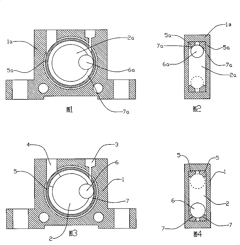
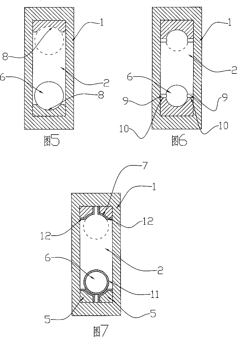
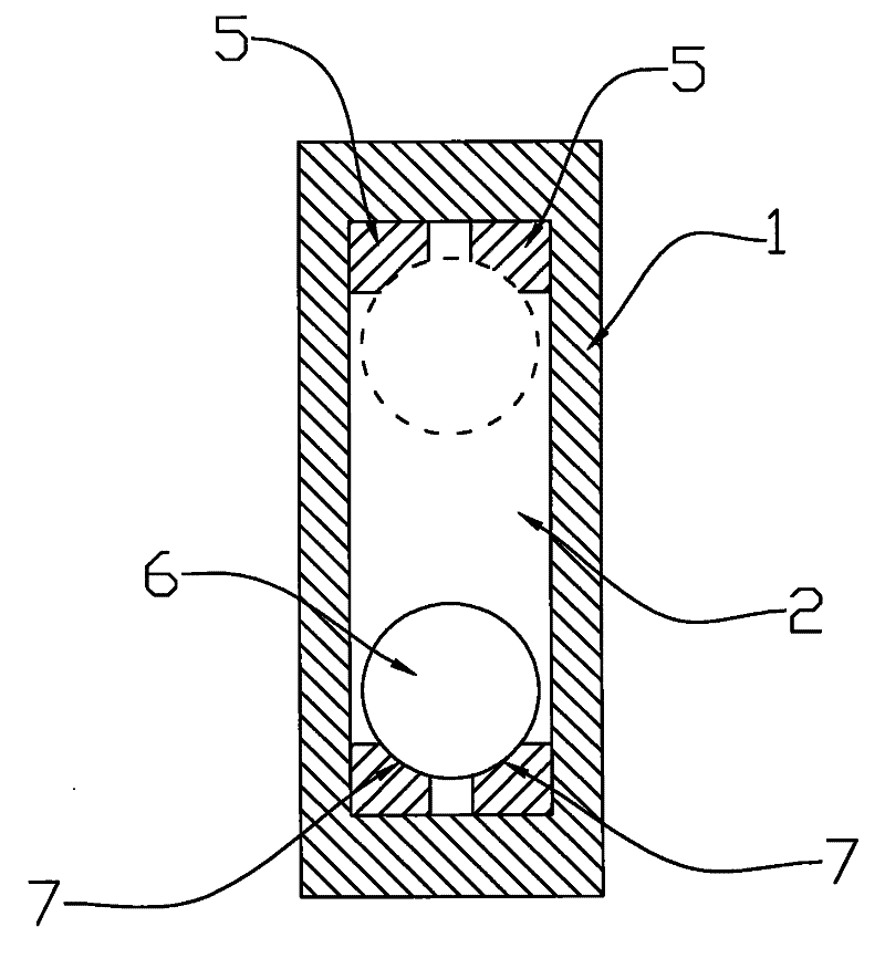
[0013] Example 1, such as image 3 , Figure 4 , a pneumatic vibrator has a housing 1, an air inlet 3 and an exhaust hole 4 communicating with the inner cavity 2 on the housing 1, two annular guide rails 5 are housed in the inner cavity of the housing, and two annular The opposite sides of the guide rails are bent downward to jointly form a track on which the ball 6 is mounted and can move along the track. The curvature of the curved surface 7 formed by the downward bending of the two circular guide rails matches the shape of the ball.

[0014] The curvature of the downward curved surface 7 on the opposite sides of the two circular guide rails 5 matches the shape of the ball 6. When the ball moves on the track formed by the two circular guide rails, it can completely fit the curved surfaces of the circular guide rails on both sides, increasing the aerodynamic force. The contact area between the vibrator ball and the track reduces the friction force and the pressure generated ...


PUM


Abstract

The invention discloses a pneumatic vibrator. The arc formed by the downward bending of two annular guide rails on the opposite side matches the curved surface of the ball shape. Fitting, which increases the contact area between the ball and the track of the pneumatic vibrator, reduces the friction force on the contact surface and the pressure generated by the collision force, makes the ball and guide rail not easy to wear, thus prolonging the service life of the vibrator.

Description

technical field [0001] The invention relates to a device for generating vibration by the action of airflow, in particular to a pneumatic vibrator. technical background [0002] In food, medicine, chemical industry, pesticide, feed, ceramics, glass, cement, fuel and other powder processing industries, in order to prevent powder from sticking, clogging and bridging when conveying in pipelines, hoppers, silos and other conveying equipment And other phenomena, it is usually necessary to install vibrators on pipelines, hoppers, silos and other conveying equipment. Pneumatic vibrators are widely used because of their safety, energy saving and wide temperature adaptability. Existing pneumatic vibrators such as figure 1 , figure 2 , including housing 1a, two annular guide rails 5a installed in the housing cavity 2a, the opposite sides of the two annular guide rails are inclined to form a track, and the ball 6a is mounted on the inclined surface 7a of the two annular guide rails,...

Claims


Application Information

Patent Timeline
Patent Type & Authority Patents(China)
IPC IPC(8): B06B1/18
Inventor 李伟文
Owner 李伟文
Why Eureka
Try Eureka