Respiration monitoring device, respiration monitoring system, medical treatment system, respiration monitoring method, and respiration monitoring program
A technology for monitoring devices and images, used in computer-aided medical procedures, assessment of respiratory organs, medical science, etc., and can solve problems such as discomfort, device entry, and obstruction
- Summary
- Abstract
- Description
- Claims
- Application Information
AI Technical Summary
Problems solved by technology
Method used
Image

Examples
no. 2 Embodiment approach
[0132] Next, a second embodiment of the present invention will be described.
[0133] Since the present embodiment is a modified example of the above-mentioned first embodiment, the same parts as those described in the first embodiment are given the same reference numerals and description thereof will be omitted. The present embodiment differs from the first embodiment described above in the calculation method of the fluctuation amount in the fluctuation amount calculation unit.
[0134] The variation calculation unit 103 of the present embodiment is configured based on the luminance of pixels on the image acquired by the image acquisition unit 102 at an arbitrary timing as an arbitrary timing and the respiratory movement achieved in the imaging target area before the arbitrary timing. The difference between the luminances of the pixels on the image obtained at the reference time of the timing of the predetermined extreme position in the image is calculated as the variation am...
no. 3 Embodiment approach
[0146] Next, a third embodiment of the present invention will be described.
[0147] Since this embodiment is a modified example of the above-mentioned first embodiment, the same parts as those described in the first embodiment are denoted by the same reference numerals and description thereof will be omitted. The present embodiment differs from the above-mentioned first embodiment in the calculation method of the fluctuation amount in the fluctuation amount calculation unit.
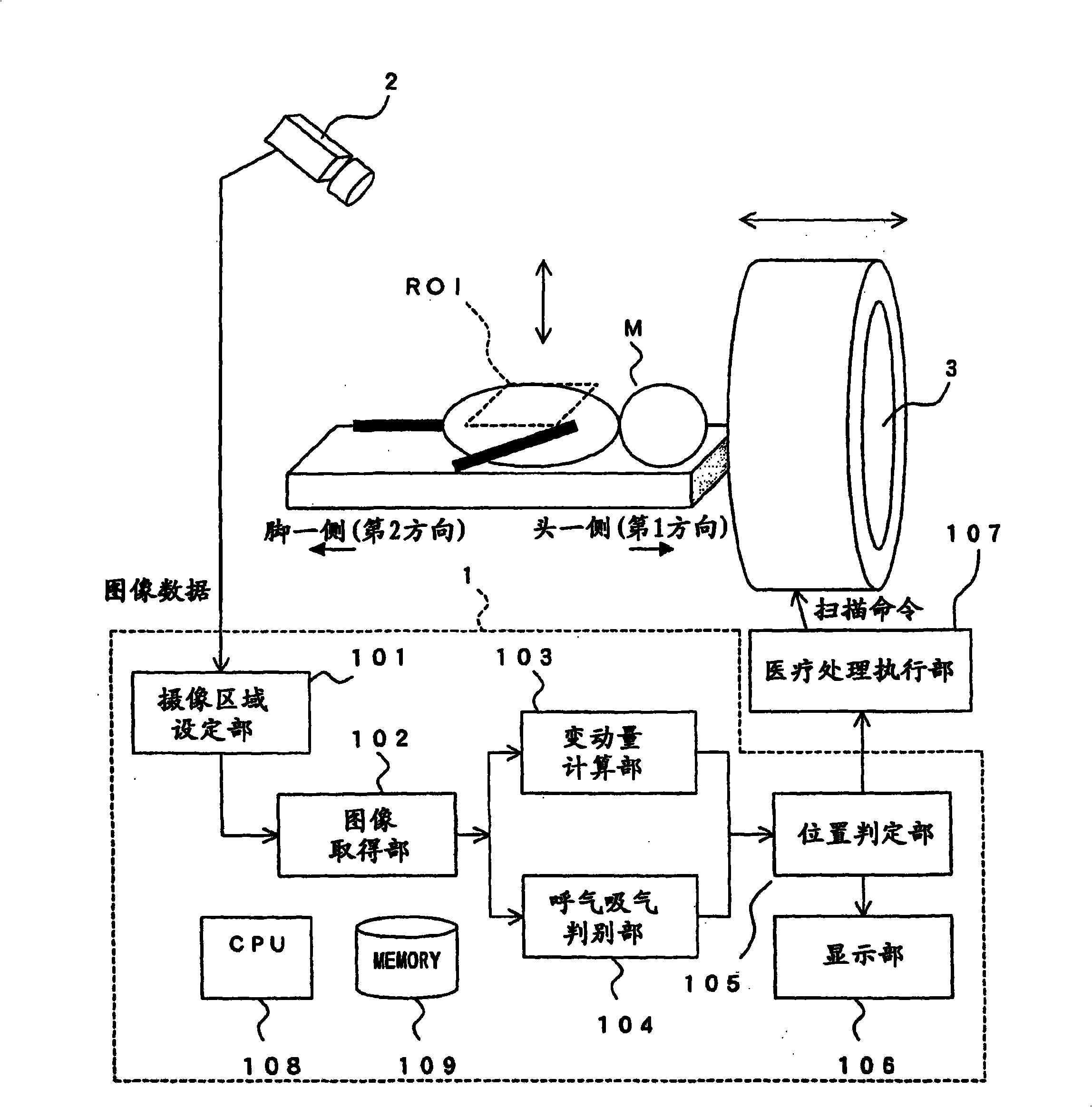
[0148] The imaging region setting unit 101 in the present embodiment is configured to set an imaging target region ROI centering on the pixel region in which the brightness of pixels on an image obtained by imaging the subject M has the largest temporal change.
[0149] In addition, the variation calculation unit 103 in the present embodiment is configured to acquire the second area of pixels having approximately the same luminance distribution as the first area from the second time point which is a p...
no. 4 Embodiment approach
[0192] Next, a fourth embodiment of the present invention will be described.
[0193] Since the present embodiment is a modified example of the above-mentioned first embodiment, the same parts as those described in the first embodiment are given the same reference numerals and description thereof will be omitted. The calculation method of the fluctuation amount in the fluctuation amount calculation unit of this embodiment is different from that of the first embodiment described above.
[0194] The variation calculation unit 103 in this embodiment is configured to extract, from within the imaging target region ROI on the image acquired by the image acquisition unit 102 at an arbitrary timing as an arbitrary timing, a region having substantially the same brightness distribution as the first region. For the second area of pixels, the moving distance from the position of the first area to the position of the second area in the imaging target area ROI is calculated as the variati...
PUM
 Abstract
Description
Claims
Application Information
 - R&D
- Intellectual Property
- Life Sciences
- Materials
- Tech Scout
- Unparalleled Data Quality
- Higher Quality Content
- 60% Fewer Hallucinations
Browse by: Latest US Patents, China's latest patents, Technical Efficacy Thesaurus, Application Domain, Technology Topic, Popular Technical Reports.
© 2025 PatSnap. All rights reserved.Legal|Privacy policy|Modern Slavery Act Transparency Statement|Sitemap|About US| Contact US: help@patsnap.com