X ray imaging apparatus and X ray imaging method

一种摄像设备、X射线的技术,应用在X射线设备、辐射安全装置、用于放射诊断的仪器等方向

Inactive Publication Date: 2008-11-12
CANON KK
View PDF1 Cites 9 Cited by
  • Summary
  • Abstract
  • Description
  • Claims
  • Application Information

AI Technical Summary

Problems solved by technology

On the other hand, however, the scheduled process has to be aborted even if it is not completed

Method used


Image

  • X ray imaging apparatus and X ray imaging method
  • X ray imaging apparatus and X ray imaging method
  • X ray imaging apparatus and X ray imaging method

Examples


no. 1 example

[0021] Structure of X-ray imaging equipment

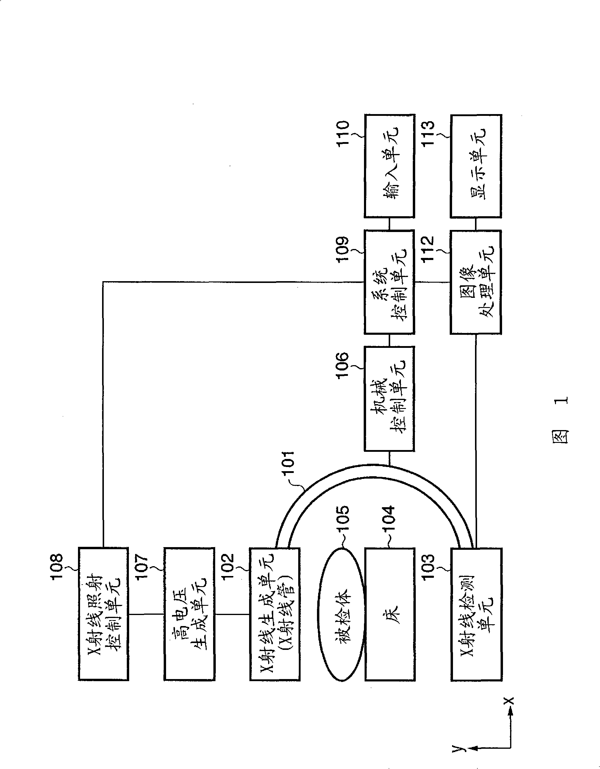
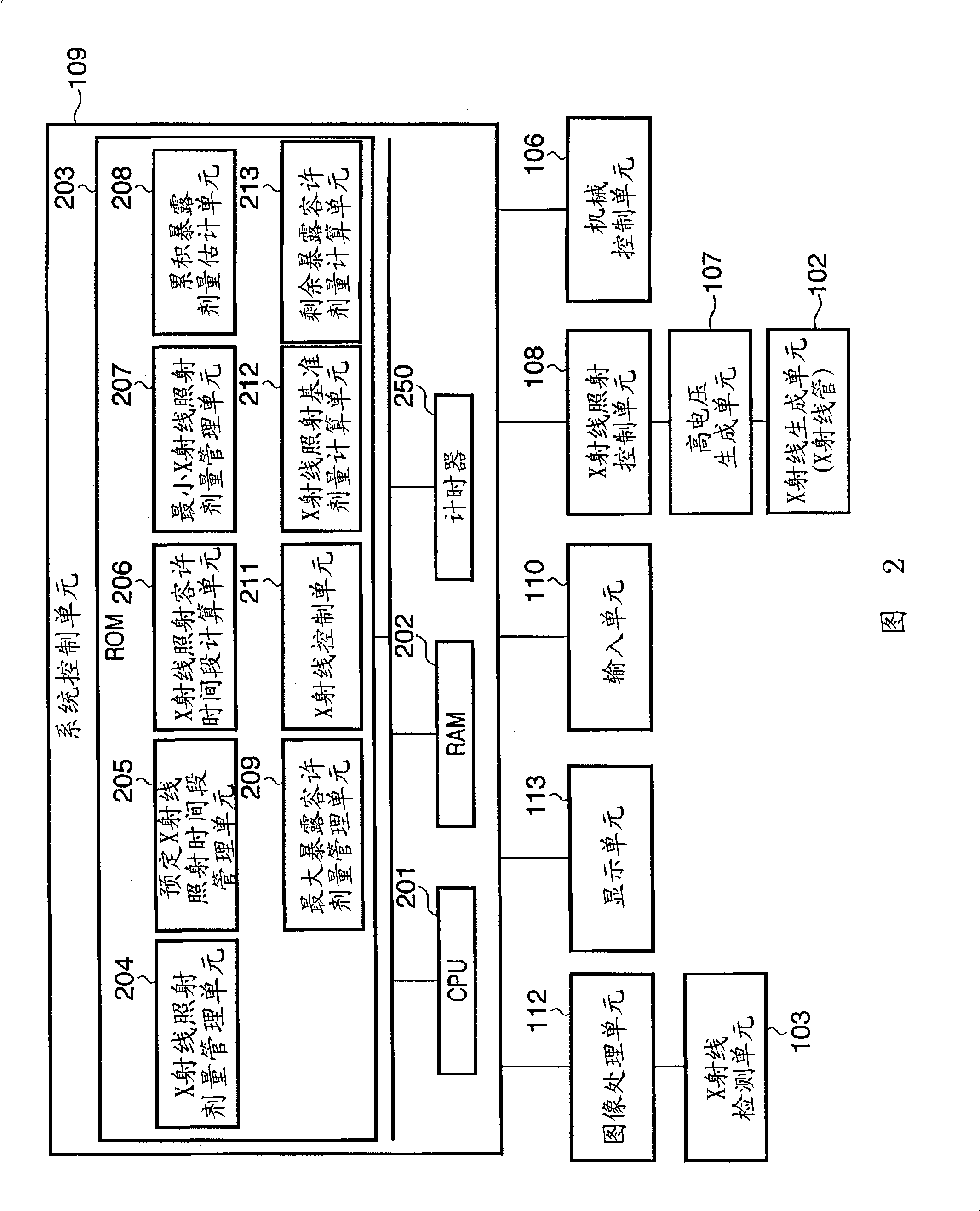
[0022] FIG. 1 shows an example of the structure of an X-ray imaging apparatus according to the present invention. An X-ray generating unit (X-ray tube) 102 is an X-ray generating source that irradiates an object (subject) 105 with X-rays. An X-ray generating unit (X-ray tube) 102 is held by one end of a holding unit 101 . The X-ray detection unit 103 is a sensor that detects X-rays irradiated from the X-ray generation unit (X-ray tube) 102 . The X-ray detection unit 103 is held by the other end of the holding unit 101 . An X-ray detection unit 103 and an X-ray generation unit (X-ray tube) 102 are held by a holding unit 101 facing each other. Note that instead of being fixed, the X-ray detection unit 103 and the X-ray generation unit (X-ray tube) 102 may be held in a state movable relative to each other as long as they continue to face each other.

[0023] A bed 104 is provided between the X-ray generation unit (X-ray tube) 10...

no. 2 example

[0074] Figure 5A with 5B is a flowchart showing the operation flow of the X-ray imaging apparatus according to the second embodiment, in which the operations of the steps are performed under the overall control of the CPU 201 . It is assumed that the X-ray imaging apparatus has a structure similar to that of FIGS. 1 and 2 explained in the first embodiment.

[0075] In step S501, the CPU 201 starts the process.

[0076] In step S502, the CPU 201 judges whether or not a trigger for starting irradiation has been input. In step S503 , the X-ray generating unit 102 performs X-ray irradiation based on the X-ray irradiation dose per unit time held by the X-ray irradiation dose management unit 204 .

[0077] In step S504, the CPU 201 determines whether to set the X-ray irradiation dose per unit time manually or automatically (automatic X-ray control) based on the operator's selection operation. If the operator's operation instructs automatic X-ray control (YES in S504), the proce...

no. 3 example

[0094] Figure 7A and 7B are flowcharts showing the operation flow of the X-ray imaging apparatus according to the third embodiment, in which the operations of the steps are performed under the overall control of the CPU 201 . It is assumed that the X-ray imaging apparatus has a structure similar to that of FIGS. 1 and 2 explained in the first embodiment.

[0095] In step S701, the CPU 201 starts the process.

[0096] In step S702, the CPU 201 judges whether or not a trigger signal for starting irradiation has been input. In step S703 , the X-ray generating unit 102 performs X-ray irradiation based on the X-ray irradiation dose per unit time held by the X-ray irradiation dose management unit 204 .

[0097]In step S704, the CPU 201 judges whether or not an instruction to calculate the X-ray irradiation reference dose per unit time has been given. If an instruction to calculate the X-ray irradiation reference dose per unit time has been given (YES in S704), the process advanc...


PUM


Abstract

An X-ray imaging apparatus includes an estimation unit (208) that estimates a cumulative exposure dose of X-rays irradiated onto an object, a remaining exposure tolerance dose calculation unit (213) that calculates a remaining exposure tolerance dose using a difference between a tolerated maximum exposure dose and the cumulative exposure dose, an X-ray irradiation tolerance period calculation unit (206) that calculates an X-ray irradiation tolerance period using a difference between a predetermined scheduled X-ray irradiation period and an actual irradiation period of X-rays irradiated onto the object, an X-ray irradiation reference dose calculation unit (212) that calculates an X-ray irradiation reference dose per unit time that will form a basis of X-ray irradiation based on the remaining exposure tolerance dose and the X-ray irradiation tolerance period, and a control unit (211); that controls X-ray irradiation onto the object by setting an X-ray irradiation dose per unit time within the X-ray irradiation tolerance period based on the X-ray irradiation reference dose.

Description

technical field [0001] The present invention relates to an X-ray imaging device and an X-ray imaging method for preventing exposing a patient to excessive doses of radiation. Background technique [0002] X-ray diagnostic imaging using X-rays has generally been applied to radiographic interpretation using still images, however, in recent years its application has been expanded to include X-ray fluoroscopy and surgical support. However, X-ray fluoroscopy and surgical support, while very beneficial, inevitably expose the patient to radiation, and the risk of exposure must always be considered when performing diagnostic X-rays and surgical support. Despite these risks, until now the X-ray dose has generally been manually adjusted by the operator providing the medical care. The operator selects the appropriate X-ray dose according to the purpose of the operation, the purpose of the inspection, the location of the inspection, the patient's physique, age and sex, and the characte...

Claims


Application Information

Patent Timeline
Patent Type & Authority Applications(China)
IPC IPC(8): A61B6/10H05G1/42G08B21/02
CPCA61B6/542A61B6/4441
Inventor 犬贺美帆吉田崇
Owner CANON KK
Why Eureka
Try Eureka