Inertia force balance method of high speed punching machine crank connecting rod sliding block mechanism

A technology of crank connecting rod and high-speed punch press, which is applied in inertia force compensation, special data processing applications, instruments, etc., can solve the problems that cannot be used in production practice, does not solve the reasonable vibration isolation method and the adjustment method of die height, and affects the high-speed punch industry. development and other issues

Inactive Publication Date: 2008-11-12
XI AN JIAOTONG UNIV
View PDF0 Cites 14 Cited by
  • Summary
  • Abstract
  • Description
  • Claims
  • Application Information

AI Technical Summary

Problems solved by technology

However, due to the large gap between our country's theoretical research level and manufacturing level of high-speed punching machines and foreign countries, the number of strokes per minute of the sliders used in domestic high-speed punching machines in industrial practice is not high, and the work is extremely unstable. Shock vibration and The noise is large, and it is almost impossible to be used in production practice, so the industry mainly relies on a large number of imported foreign high-speed punching machines
Due to the confidentiality of technology, there are almost no relevant literature reports on the design theory and methods of high-speed punching

Method used


Image

  • Inertia force balance method of high speed punching machine crank connecting rod sliding block mechanism
  • Inertia force balance method of high speed punching machine crank connecting rod sliding block mechanism
  • Inertia force balance method of high speed punching machine crank connecting rod sliding block mechanism

Examples


Embodiment Construction

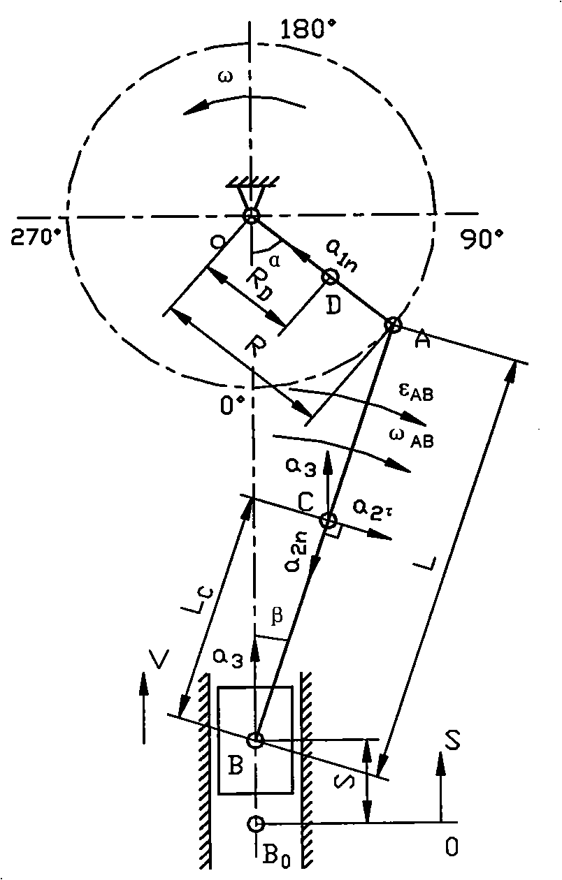
[0073] The method of the present invention will be further described in detail below in conjunction with the accompanying drawings.

[0074] 1. On the basis of the motion analysis of the centering upright crank connecting rod slider mechanism with the crank rotation angular velocity as a constant, the accurate and simplified expressions of the displacement, velocity and acceleration of the slider of the mechanism and the swing angular velocity of the connecting rod are established ; The expressions of the centripetal acceleration of the crank mass center, the translation of the connecting rod mass center, centripetal and tangential accelerations and the angular acceleration of the connecting rod swing are obtained further. Such as figure 1 As shown, points C and D in the figure are the centroids of connecting rod AB and crank OA respectively; and there are OA=R, OD=R D , AB=L, AC=L A ,BC=L C , crank mass m 1 , slider mass m 2 , connecting rod mass m 3 . The connecting r...


PUM


Abstract

The invention discloses a method for balancing the inertial force of a crank lingage slider mechanism of a high speed punching machine, which is characterized in that: the mechanism that the crank lingage slider mechanism produces inertial force is disclosed, a correct calculating formula of the balancing mass of an eccentric block of a large gear on a crankshaft when the inertial force is in total balance is derived by taking the total balance of the inertial force as the design thought and the crank lingage slider mechanism with fully symmetric double-point or four-point double cranks as the basis, thus realizing the purpose of reaching the balance of the inertial force at a vertical direction by adjusting the mass of the eccentric block according to different mass of moulds, and obtaining good dynamic balance effect from the practical application in 1000kN high speed punching machine industry.

Description

technical field [0001] The invention relates to a method for balancing the inertial force of forging equipment, in particular to a method for balancing the inertial force of a high-speed punch press crank connecting rod slider mechanism. Background technique [0002] In recent years, with the rapid development of electronics, communications, computers, home appliances and automobile industries, the demand for functional stamping parts that tend to be standardized and serialized in size and shape has grown rapidly. Such parts are very suitable for mass production on high-speed punching machines, so in order to reduce costs and improve labor productivity, high-speed punching machines are more and more widely used in industrial practice. However, due to the large gap between our country's theoretical research level and manufacturing level of high-speed punching machines and foreign countries, the number of strokes per minute of the sliders used in domestic high-speed punching m...

Claims


Application Information

Patent Timeline
IPC IPC(8): F16F15/26G06F17/50
Inventor 赵升吨王军郝永江
Owner XI AN JIAOTONG UNIV
Why Eureka
Try Eureka