Optical system evaluation apparatus, optical system evaluation method and program thereof

一种光学系统、评价装置的技术,应用在测量装置、光学仪器测试、测试光学性能等方向,能够解决评价精度降低、光学特性评价精度降低、很难确保光学系统光学系统评价装置稳定性等问题

Active Publication Date: 2008-11-12
EVIDENT CORP
View PDF2 Cites 56 Cited by
  • Summary
  • Abstract
  • Description
  • Claims
  • Application Information

AI Technical Summary

Problems solved by technology

[0010] However, like the above-mentioned conventional optical system evaluation device, there is the following problem: the imaging position of the point image corresponding to one hole is obtained and the image plane In this method that is repeated at multiple positions in the interior, it is necessary to use some length measuring machine to monitor the position of the hole and the position of the magnifying optical system for point image observation, corresponding to the measurement accuracy of the length measuring machine, and the optical characteristics Decrease in evaluation accuracy
In addition, there is also the following problem: in order to measure while moving one hole, it takes a lot of time to measure the entire range of the field of view, and it is difficult to ensure the stability of the optical system of the evaluation object and the optical system evaluation device during the period. , the evaluation accuracy decreases

Method used


Image

  • Optical system evaluation apparatus, optical system evaluation method and program thereof
  • Optical system evaluation apparatus, optical system evaluation method and program thereof
  • Optical system evaluation apparatus, optical system evaluation method and program thereof

Examples


no. 1 Embodiment approach

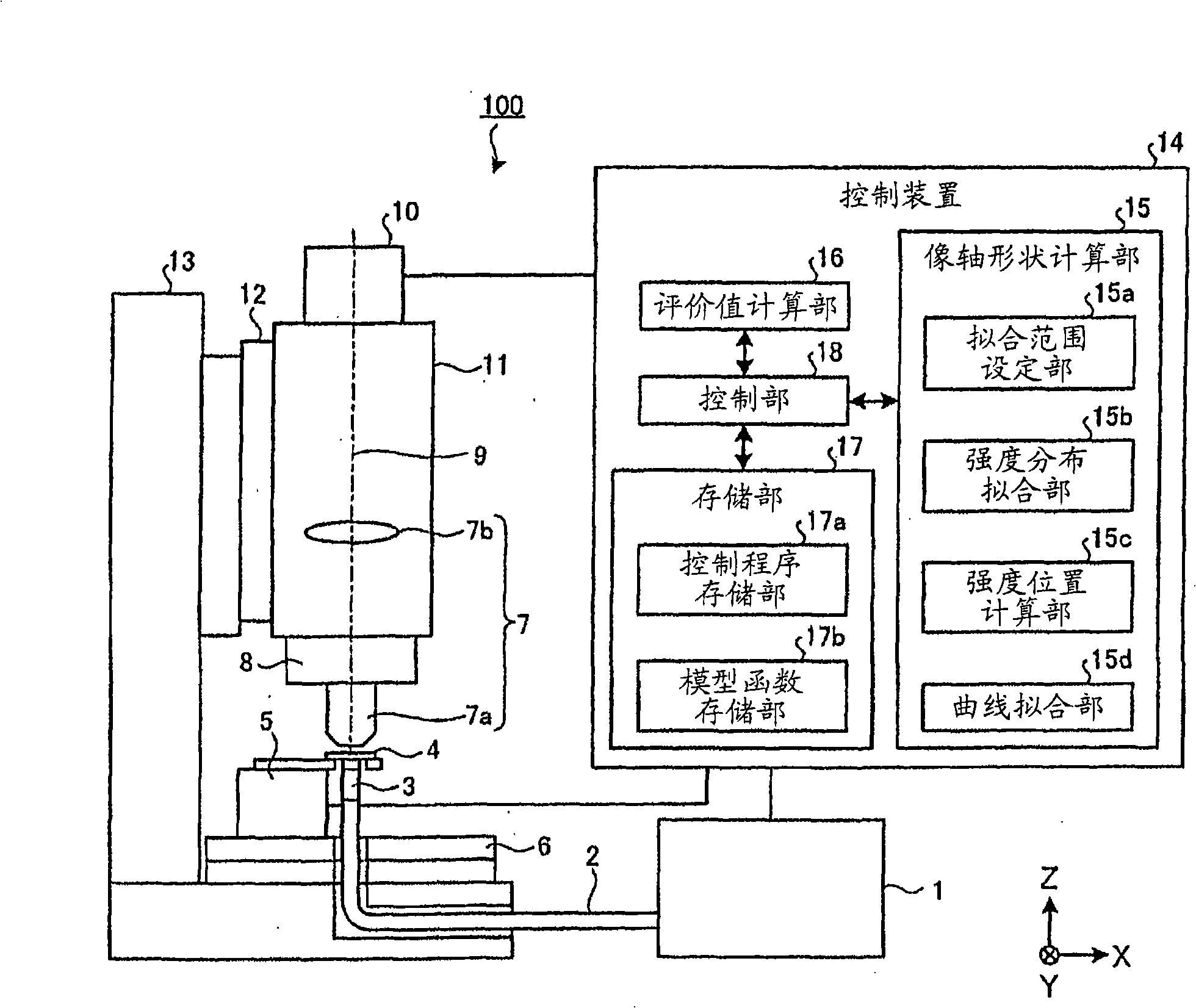
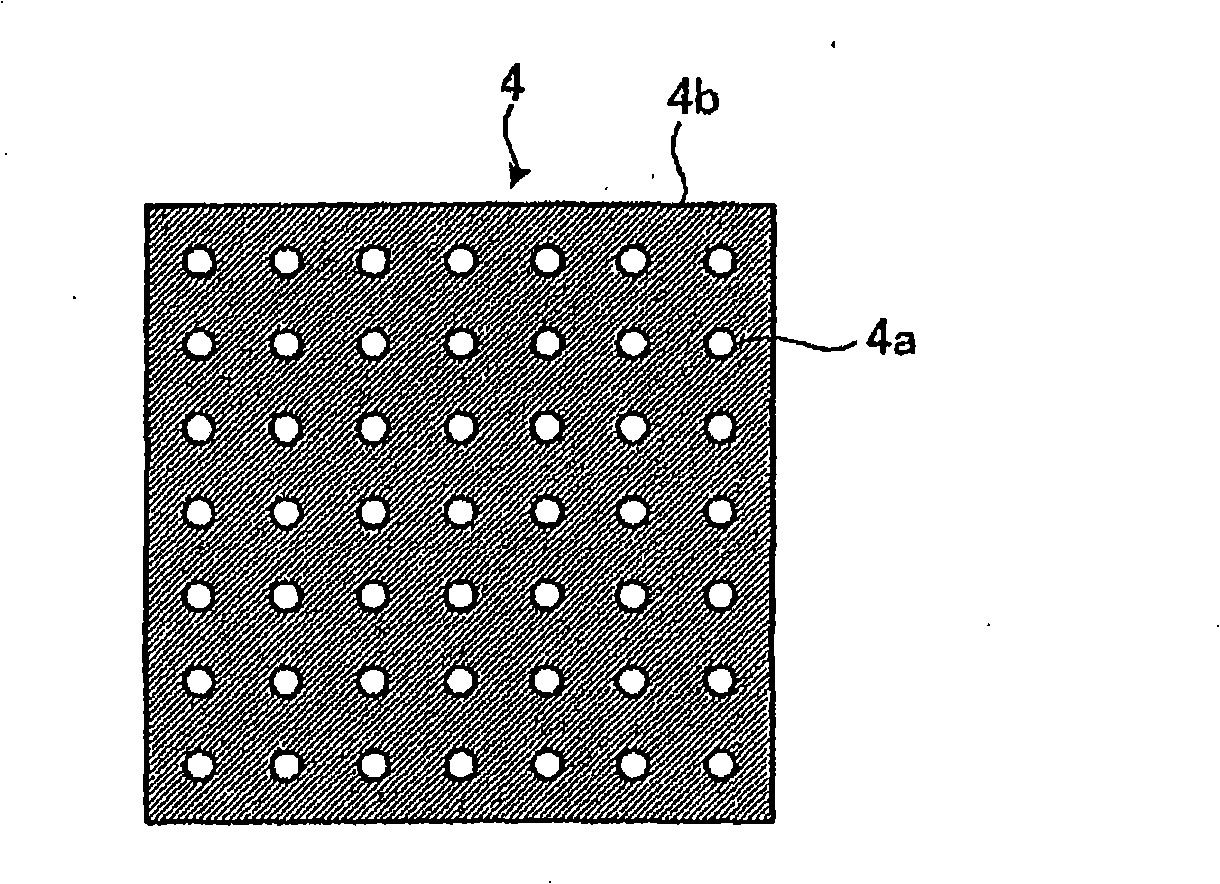
[0052] First, an optical system evaluation device according to Embodiment 1 of the present invention will be described. figure 1 It is a figure showing the structure of the main part of the lens evaluation apparatus 100 which is the optical system evaluation apparatus of this Embodiment 1. FIG. As shown in this figure, the lens evaluation device 100 includes: a sample 4 with a plurality of holes arranged in a planar shape; a light source 1, which serves as an illumination unit for illuminating the sample 4; an optical fiber 2 and a light intensity uniformizing unit 3; The object table 5 as a moving unit holds and moves the sample 4 in the Z-axis direction; and the XY stage 6 moves the sample 4 in the X-axis direction and the Y direction.

[0053] In addition, the lens evaluation device 100 includes: an imaging lens 7b constituting the microscope optical system 7 and imaging the observation image of the sample 4 together with the objective lens 7a as the evaluation object opti...

Embodiment approach 2

[0133] Next, an optical system evaluation device according to Embodiment 2 of the present invention will be described. Figure 10 It is a diagram showing the configuration of main parts of a fluorescence confocal microscope 200 as an optical system evaluation device according to the second embodiment. As shown in the figure, the fluorescent confocal microscope 200 includes a laser light source 51, a dichroic mirror 53, an XY scanner 54, a total reflection mirror 55, an objective lens system 56, a sample 57, a Z-axis stage 58, and a confocal optical system 59 . A light detection system 60 , a control unit 61 , a computer 62 and a display unit 63 .

[0134] Illumination light (excitation light) from a laser light source 51 selectively emitting laser light of multiple wavelengths passes through an XY scanner 54 and a total reflection mirror 55 , and then is condensed by an objective lens system 56 at a focal position within a sample 57 . The reflected light (fluorescence) from t...


PUM


Abstract

An apparatus (100) is for evaluating optical characteristics of an optical system (7a) based on an image forming position of a point image formed through the optical system (7a). The apparatus (100) includes a point image producing unit (1 to 4; 4b) that forms a point image through the optical system (7a) in each point light source; an imaging unit (10) that images the point images to produce a point image distribution image; and a moving unit (5) that changes relative distance between the optical system (7a) and the point light source or the imaging unit (10) in an optical axis direction (9).; The apparatus (100) also performs processing of detecting an image forming position in each different relative distance of the point image based on image information of the point image distribution images, the processing including calculating a regression expression for the detected image forming positions to obtain a shape parameter of the image axis in each of the point images.

Description

[0001] References to related applications [0002] This application claims priority from Japanese Patent Application No. 2007-124682 filed on May 9, 2007 and incorporates the entire contents thereof. technical field [0003] The present invention relates to an optical system evaluation device, an optical system evaluation method, and an optical system evaluation program for evaluating optical characteristics of an evaluation object optical system based on an imaging position of a point image formed through the evaluation object optical system. Background technique [0004] In general, when an image captured using an optical system is used for length measurement, a high degree of telecentricity (telecentricity) is required in the optical system. The so-called telecentricity means that the chief ray on the object side or the image side is parallel to the optical axis regardless of the distance from the optical axis. For example, in a length measuring microscope, an object-sid...

Claims


Application Information

Patent Timeline
Patent Type & Authority Applications(China)
IPC IPC(8): G01M11/02
CPCG01M11/0228G01M11/0257
Inventor 松沢聪明
Owner EVIDENT CORP
Why Eureka
Try Eureka