Longitudinal-shaking sandwich energy converter type cylinder type birotor ultrasonic motor

A technology of ultrasonic motors and transducers, applied in the direction of generators/motors, piezoelectric effect/electrostrictive or magnetostrictive motors, electrical components, etc., can solve the problem of low electromechanical coupling efficiency and mechanical output capacity constraints of a single stator Problems such as single motion output and poor mechanical output ability can achieve the effect of improving controllability, eliminating adverse effects, and simplifying the structure

Inactive Publication Date: 2008-11-12
HARBIN INST OF TECH
View PDF0 Cites 6 Cited by
  • Summary
  • Abstract
  • Description
  • Claims
  • Application Information

AI Technical Summary

Problems solved by technology

[0003] In order to solve the problems existing in the existing ultrasonic motors that the mechanical output capability is restricted due to the use of metallic elastic bodies pasted with piezoelectric ceramic sheets for excitation and that a single stator can only achieve a single motion output, a longitudinal vibration motor is provided. Sandwich transducer type cylindrical double rotor ultrasonic motor
[0005] In the ultrasonic motor provided by the present invention, the piezoelectric ceramic element adopts a sandwich structure, and adopts the d33 mode with high electromechanical coupling efficiency of piezoelectric ceramics to work , to solve the problems of low electromechanical coupling efficiency and poor mechanical output capability of pasted piezoelectric ceramic chip piezoelectric ultrasonic motors, and also simplify the structure through the integrated structure of the front end cover and the stator cylinder, and improve the vibration trajectory of the surface particles of the cylindrical elastic body Controllability, eliminating the adverse effects on the vibration waveform of the stator caused by connecting the transducer and the cylinder in other ways

Method used


Image

  • Longitudinal-shaking sandwich energy converter type cylinder type birotor ultrasonic motor
  • Longitudinal-shaking sandwich energy converter type cylinder type birotor ultrasonic motor
  • Longitudinal-shaking sandwich energy converter type cylinder type birotor ultrasonic motor

Examples


specific Embodiment approach 1

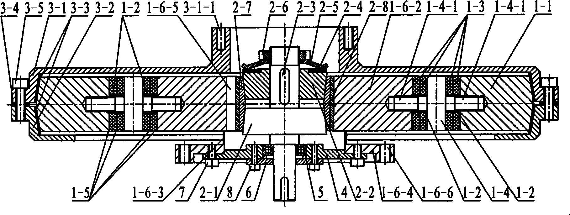
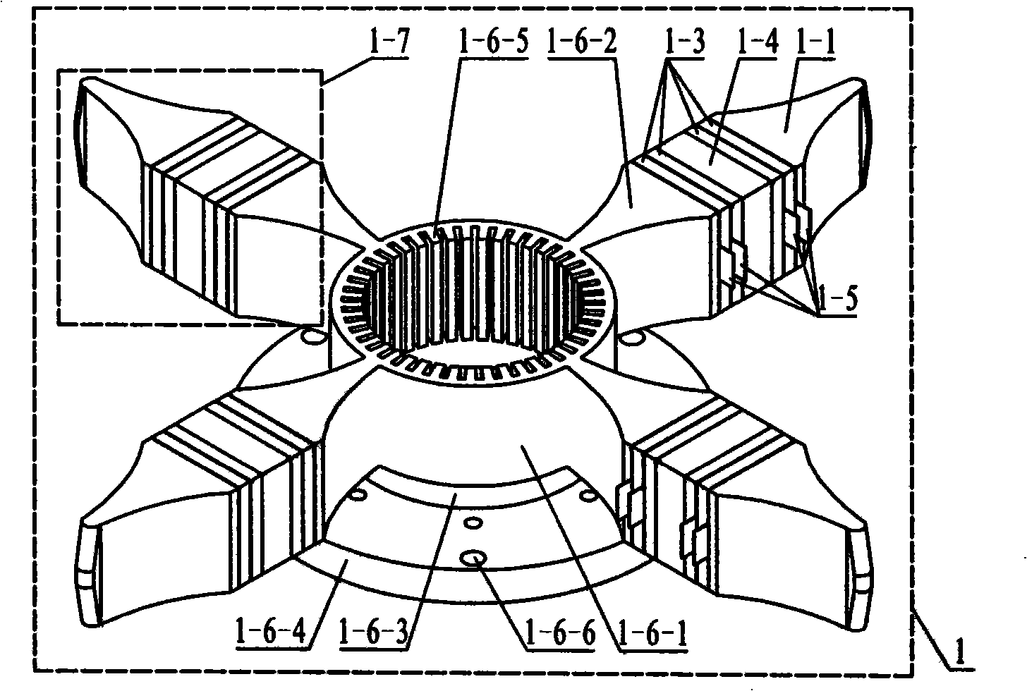
[0010] Specific implementation mode one: see Figure 1 to Figure 11, this embodiment is composed of a stator assembly 1, an inner rotor assembly, an outer rotor assembly, a bearing housing 4, a bearing 5, a bearing preload end cover 6, a second screw group 7 and a third screw group 8; the stator assembly 1 is composed of The driving cylinder 1-6 is composed of 2n longitudinal vibration sandwich transducers 1-7, wherein n is a natural number greater than 1, and the 2n longitudinal vibration sandwich transducers 1-7 are symmetrically distributed and fixedly connected to the driving circle Outside the side wall of the barrel 1-6, the longitudinal vibration sandwich transducer 1-7 consists of a front end cover 1-6-2, a rear end cover 1-1, an insulating sleeve 1-2, and two pairs of piezoelectric ceramic sheets 1-3 , flange 1-4 and two pairs of copper electrode sheets 1-5, the front end cover 1-6-2 and the rear end cover 1-1 are quadrangular prisms whose sections are all rectangular...

specific Embodiment approach 2

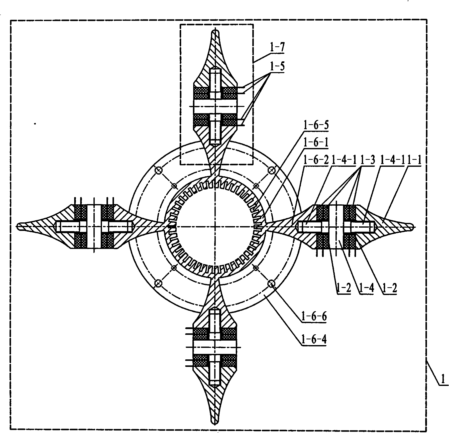
[0012] Specific implementation mode two: see Figure 5 The difference between this embodiment and the first embodiment is that the cylinder 1-6-1, the front end cover 1-6-2, the thin-walled ring 1-6-3 and the cylinder flange 1-6-4 adopt a The whole piece of metal material is processed into an integral part of the drive cylinder, and a number of evenly distributed threaded holes 1-6-6 are processed on the cylinder flange 1-6-4, and the threaded holes 1-6-6 are connected with the inner belt shaft. The output shafts of the rotor 2-1 are parallel.

[0013] In this embodiment, the cylinder 1-6-1, the front end cover 1-6-2, the thin-walled ring 1-6-3 and the cylinder flange 1-6-4 are processed into one component, which can reduce energy The purpose of the loss is beneficial to improve the controllability of the vibration trajectory of the surface particle of the drive tooth 1-6-5; the threaded hole 1-6-6 can be used to realize the installation of the motor in the mechanical system....

specific Embodiment approach 3

[0014] Specific implementation mode three: see Figure 4 The difference between this embodiment and the first embodiment is that the piezoelectric ceramic sheets 1-3 are polarized along the thickness direction, and the polarization directions of the two piezoelectric ceramic sheets in each pair of piezoelectric ceramic sheets 1-3 on the contrary.


PUM


Abstract

The invention discloses a longitudinal vibration sandwiched transducer type cylindrical dual-rotor ultrasonic motor, which relates to the technical field of an ultrasonic motor and aims at solving the problems that the mechanical output capacity is restricted and a single stator can only realize single moving output existing in present ultrasonic motor. The longitudinal vibration sandwiched transducer type cylindrical dual-rotor ultrasonic motor of the invention comprises a stator component, a medial rotor component, an outer rotor component, a bearing base, a bearing and a bearing pretension cover. The inner surface of a cylinder is manufactured with continuous comb-shaped driving gears; a medial rotor with a shaft and a medial rotor without the shaft are cone-shaped, the thin ends of the medial rotor with the shaft and the medial rotor without the shaft are respectively inserted from the lower part of a stator cylinder and the upper part of the stator cylinder; an outer rotor with the shaft and an outer rotor without the shaft are respectively arranged on the upper part of the stator component and the lower part of the stator component; the lateral surfaces that the outer rotor with the shaft and the outer rotor without the shaft are contacted with the back end cover of the stator are respectively fixed with wear-resistance lining rings; the medial rotor with the shaft is rotatablely connected with the bearing base by the bearing. The longitudinal vibration sandwiched transducer type cylindrical dual-rotor ultrasonic motor of the invention can be applied to the ultrasonic motor manufacturing field.

Description

technical field [0001] The invention relates to a longitudinal vibration sandwich transducer-type cylindrical double-rotor ultrasonic motor, which belongs to the technical field of piezoelectric ultrasonic motors. Background technique [0002] Piezoelectric ultrasonic motor is a kind of piezoelectric ultrasonic motor that uses the inverse piezoelectric effect of piezoelectric ceramics to excite vibration in the ultrasonic frequency range in the elastic body, and forms a particle motion with a specific trajectory at a specific point or area on the surface of the elastic body, and then passes through the stator, The frictional coupling between the rotors converts the microscopic motion of the particle into the macroscopic motion of the rotor. It has the advantages of low speed and high torque, no need for a transmission mechanism, no electromagnetic interference, fast response, and self-locking when power is off. As a piezoelectric driver, it has Very broad application prospec...

Claims


Application Information

Patent Timeline
Patent Type & Authority Applications(China)
IPC IPC(8): H02N2/00H02N2/10
Inventor 刘军考刘英想陈维山谢涛石胜君
Owner HARBIN INST OF TECH
Why Eureka
Try Eureka