Intelligent antenna calibration network and calibration method

A smart antenna and network technology, applied in diversity/multi-antenna system, space transmit diversity, transmission monitoring and other directions, can solve the problems of not being calibrated, inconsistent feeding network, etc., and achieve the effect of improving accuracy

Inactive Publication Date: 2008-11-12
MOBILE ANTENNA TECH SHENZHEN
View PDF0 Cites 11 Cited by
  • Summary
  • Abstract
  • Description
  • Claims
  • Application Information

AI Technical Summary

Problems solved by technology

[0006] The purpose of the embodiments of the present invention is to provide a smart antenna calibration network, aiming to solve the problem that the existing calibration network is set at the main feeder of the feed network, resulting in the inconsistency of the feed network itself not being calibrated

Method used


Image

  • Intelligent antenna calibration network and calibration method
  • Intelligent antenna calibration network and calibration method
  • Intelligent antenna calibration network and calibration method

Examples


Embodiment Construction

[0022] In order to make the object, technical solution and advantages of the present invention clearer, the present invention will be further described in detail below in conjunction with the accompanying drawings and embodiments. It should be understood that the specific embodiments described here are only used to explain the present invention, not to limit the present invention.

[0023] In the embodiment of the present invention, the calibration network is set on the branch of the feed network, so that the inconsistency of the feed network itself is also calibrated.

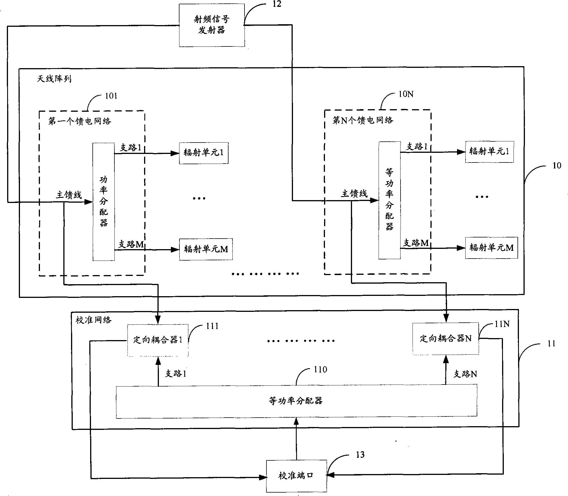
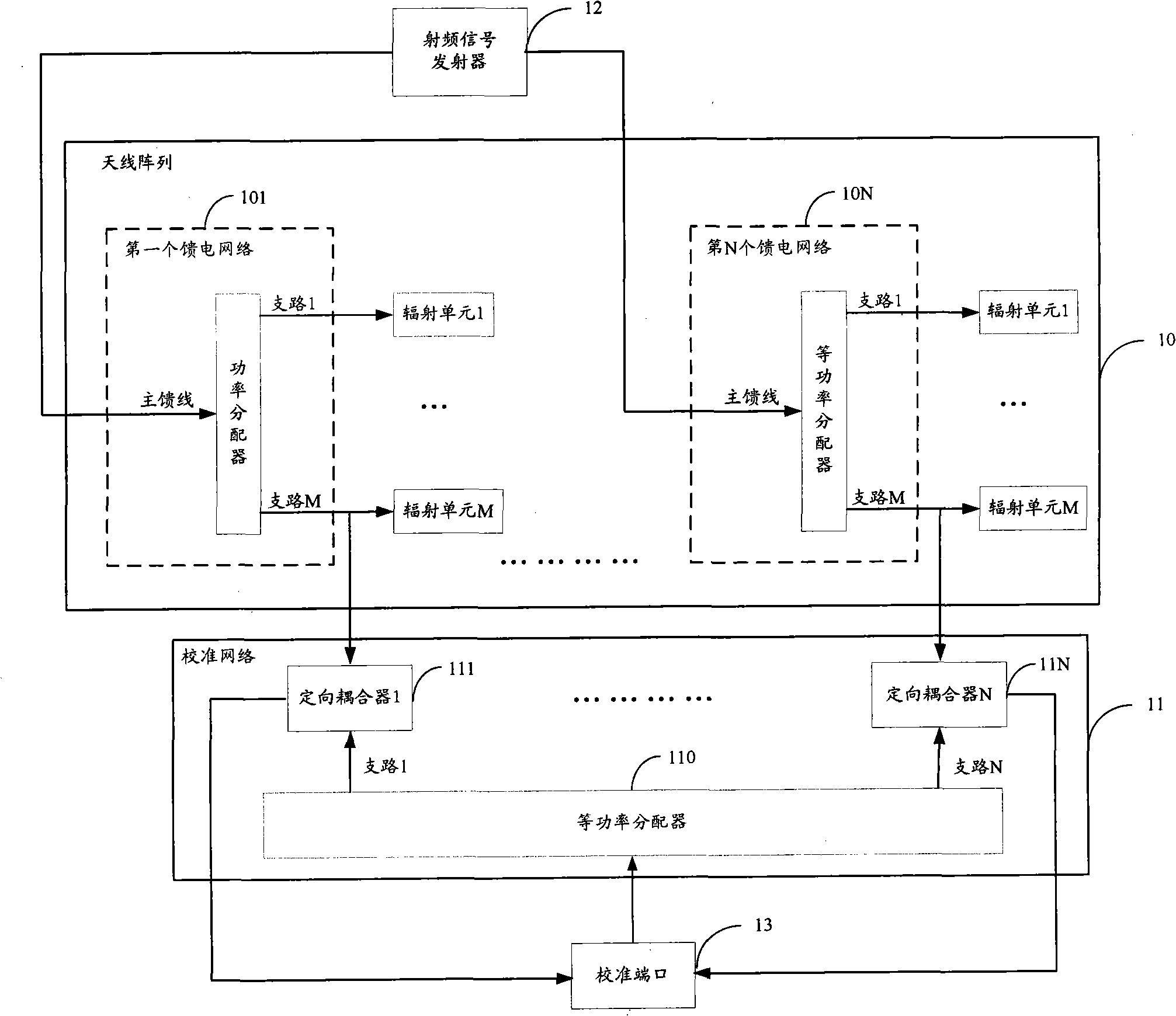
[0024] The structure of the smart antenna calibration network provided by the embodiment of the present invention is as follows figure 2 As shown, for ease of description, only the parts related to the embodiment of the present invention are shown, and the details are as follows.

[0025] The smart antenna calibration network includes: an antenna array 10 and a calibration network 11, the antenna array 10 in...


PUM


Abstract

The invention provides an intelligent antenna calibration network and a calibration method thereof, which are suitable in the antenna field. The calibration network comprises N feed networks, N columns of radiators, N directional couplers and an equal-power distributor; wherein, the radiator of each column comprises M radiation units; a main feed line of each feed network is connected to a radio frequency signal launcher; the M branches are respectively connected to the M radiation units; radio frequency signals launched by the radio frequency signal launcher are distributed to the M radiation units through the M branches; one end of the directional couplers is connected to some branch of the feed network while the other end is connected to a branch of the equal-power distributor; after the branch of the equal-power distributor is coupled with some branch of the feed network, the signals are output to a calibration port. The intelligent antenna calibration network provided by the invention respectively couples each branch in the equal-power distributor with the corresponding some branch in the feed network through the directional coupler; the self unconformity of the feed network is calibrated too, thus improving the calibration precision.

Description

technical field [0001] The invention belongs to the field of antennas, in particular to an intelligent antenna calibration network and a calibration method thereof. Background technique [0002] The smart antenna is a two-way antenna installed on the base station site. It obtains directivity through a set of fixed antenna units with programmable electronic phase relationship, and can simultaneously obtain the directional characteristics of each link between the base station and the mobile station. The smart antenna directs the radio signal to a specific direction, generates a spatially directional beam, aligns the main beam of the antenna with the direction of arrival of the user signal (Direction of Arrinal, DOA), and aligns the side lobes or nulls with the direction of arrival of the interference signal to achieve full and efficient use The purpose of moving user signals and removing or suppressing interfering signals. [0003] When the smart antenna is used, it is requir...

Claims


Application Information

Patent Timeline
Patent Type & Authority Applications(China)
IPC IPC(8): H04B17/00H04B7/06H04B17/12
Inventor 侯小强韩香紫
Owner MOBILE ANTENNA TECH SHENZHEN
Why Eureka
Try Eureka