Drafting mechanism for spinning machine

A technology of stretching system and spinning machine, applied in the field of stretching system, to achieve the effects of simple replaceability, high degree of automation, and simple structural design

Inactive Publication Date: 2008-11-19
SAURER GERMANY GMBH & CO KG
View PDF1 Cites 2 Cited by
  • Summary
  • Abstract
  • Description
  • Claims
  • Application Information

AI Technical Summary

Problems solved by technology

However, in particular, in order to reduce the production costs of the stretching system, the installation of the lower rolls is on the one hand for the adjustability of the stable and reliable installation, and on the other hand for the ease of maintenance (i.e., the easy accessibility and easy replacement of the lower rolls) arrangement) is a particular challenge

Method used


Image

  • Drafting mechanism for spinning machine
  • Drafting mechanism for spinning machine
  • Drafting mechanism for spinning machine

Examples


Embodiment Construction

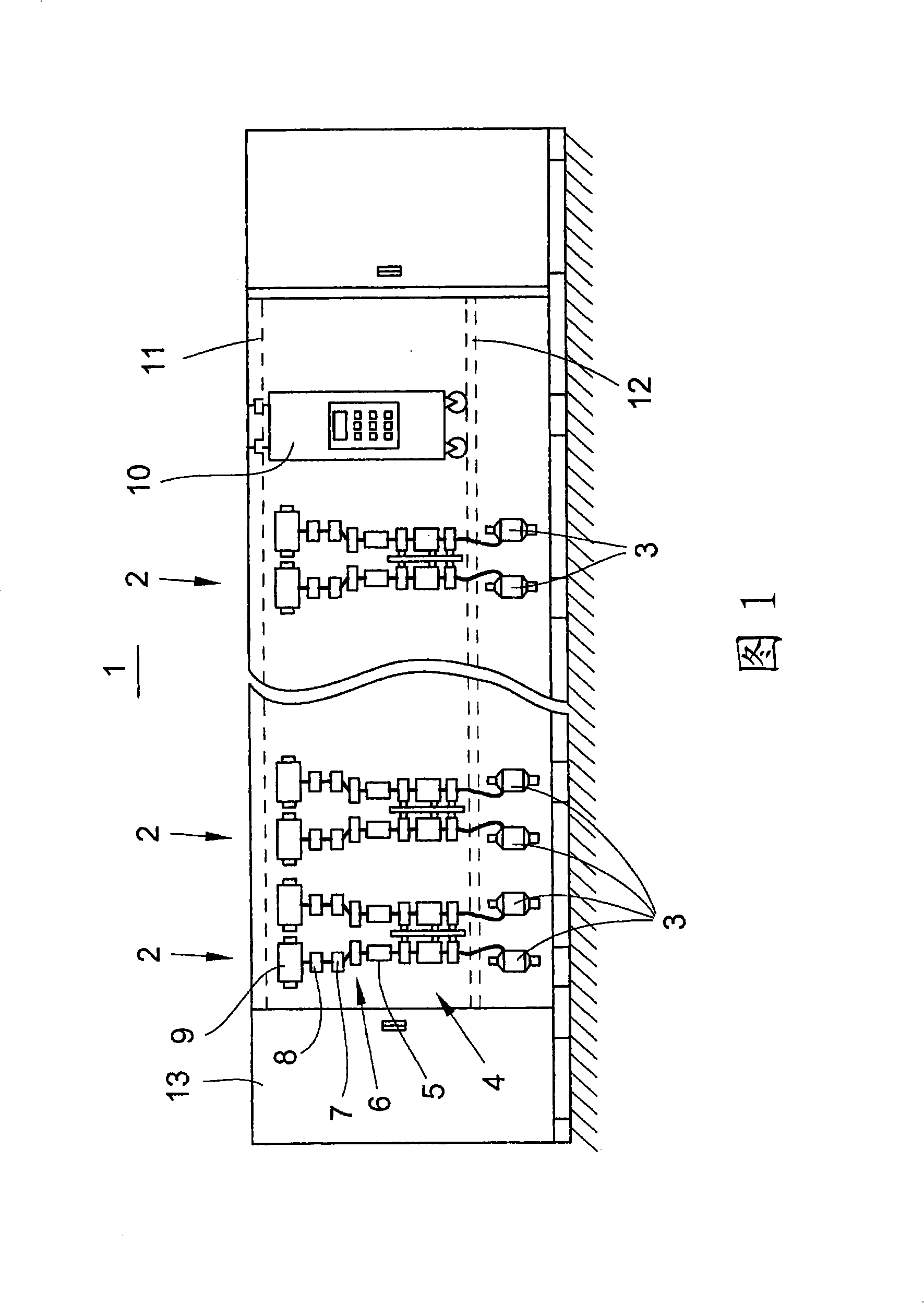
[0016] The stretching system according to the invention is described below with the aid of an air spinning machine 1 , but it can also be used in a ring spinning machine.

[0017] The air spinning machine 1 shown in FIG. 1 has a number of spinning stations 2 arranged in a row one behind the other. Each spinning station 2 comprises: a source of fiber tape configured to supply bobbins 3 from which the fiber tape is supplied to the drawing system 4; a spinning device 5; a pair of take-off rollers 6; a yarn clearer 7; a thread movement mechanism 8 ; and a winding bobbin configured as a cross-winding bobbin 9 . A service carriage 10 can move along the spinning station 2 on rails 11 , 12 . The drive unit 13 is arranged at one end of the air spinning machine 1 .

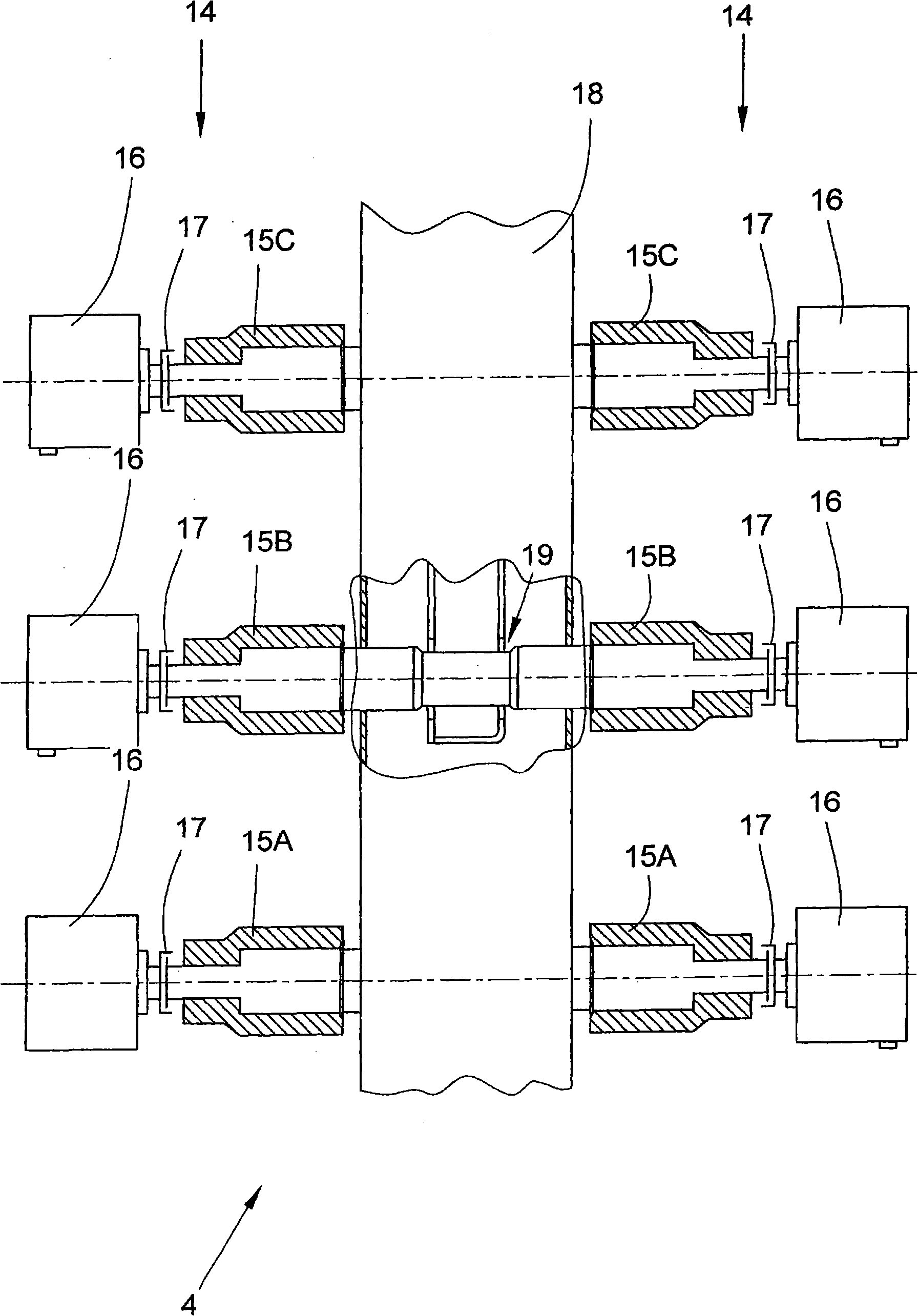
[0018] figure 2 A schematic partial sectional view of a stretching system 4 with two stretching system workstations 14 is shown. The stretching system 4 comprises a carriage 18 on which pairs of rollers are arranged for...


PUM


Abstract

The invention relates to a tension system (4) for spinning machine. The tension system (4) is provided with plural pairs of rollers respectively having drivable lower rollers (15A, 15B, 15C) and corresponding upper rollers that can be freely and rotatably mounted. The tension system (4) has two tension system working stations (14), wherein the lower rollers (15A, 15B, 15C) that are coaxially arranged and mutually separated are respectively freely and rotatably mounted on the shaft (20) in pairing. The shaft (20) is such configured in the central area (22) extending among the lower rollers (15A, 15B, 15C) that the lower rollers are easily fixed within the corresponding receiving part (19) of the bracket (18) of the tension system (18) and are easily removed from the receiving part again.

Description

technical field [0001] The invention relates to a drawing system for a spinning machine according to the preamble of claim 1 . Background technique [0002] From DE 39 32 614 A1 a drawing system is known for being equipped with two drawing system workstations for an air spinning machine, which drawing system is equipped with pairs of rollers. The multiple pairs of rollers respectively have a lower roller that can be driven by a separate motor and an upper roller that is freely installed. From DE 39 32 614 A1 it can be seen that the lower rollers are arranged on the carriages of the stretching system, but it is not explained how these lower rollers are mounted on the carriages. However, in particular, in order to reduce the production cost of the stretching system, the installation of the lower rolls is on the one hand for the adjustability of the stable and reliable installation, and on the other hand for the ease of maintenance (i.e., the easy accessibility and easy replac...

Claims


Application Information

Patent Timeline
Patent Type & Authority Applications(China)
IPC IPC(8): D01H1/22D01H5/00D01H5/56
CPCD01H1/22D01H5/26D01H5/56D01H5/74
Inventor 罗塔尔·温岑
Owner SAURER GERMANY GMBH & CO KG
Why Eureka
Try Eureka