Copper tube connection device and method

A connection device, copper pipe technology, applied in non-detachable pipe connections, pipes/pipe joints/fittings, piping systems, etc., can solve problems such as capillary blockage, refrigerant leakage, etc.

Inactive Publication Date: 2008-11-19
忠州大学校产学协力团
View PDF2 Cites 4 Cited by
  • Summary
  • Abstract
  • Description
  • Claims
  • Application Information

AI Technical Summary

Problems solved by technology

However, there is a problem with this structure that if there is any difference between the outer diameter of the capillary tube 10 and the inner diameter of the other tube 11, or if the welder's inexperience causes poor weldi

Method used


Image

  • Copper tube connection device and method
  • Copper tube connection device and method
  • Copper tube connection device and method

Examples


Embodiment Construction

[0033] Exemplary embodiments of the present invention will be described below with reference to the accompanying drawings. In the following description and drawings, the same symbols are used to indicate the same or similar components, so repeated descriptions about the same or similar components will not be repeated here.

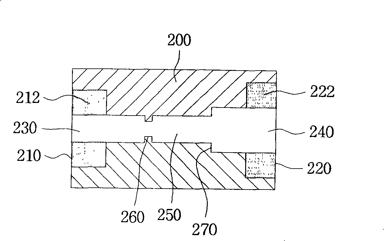
[0034] figure 2 is a schematic structural view of the copper pipe connection device according to the first embodiment of the present invention; image 3 is a schematic diagram of the principle of use of the copper pipe connecting device according to the first embodiment of the present invention.

[0035] refer to figure 2 , the copper tube connection device comprises a hollow body 200 with a hollow portion, so that the copper tube can be inserted into the hollow body; a copper tube insertion hole 230 processed on the first end of the body 200, the first diameter of which corresponds to the copper tube The diameter of the pipe 100; a second pipe inserti...


PUM


Abstract

The invention discloses a copper tube connecting apparatus for connecting a copper tube with another tube to facilitate welding operation in the refrigerating device. The new apparatus will reduce the poor welding rate so that it will effectively prevent clogging of the copper tubes and leaking the refrigerant. It also has merit to easily determine a suitable heating time while the copper tubes are welding. Thus, the rate of poor welding is reduced, as well as a method for connecting copper tubes by using the tube connecting apparatus.

Description

technical field [0001] The present invention relates to a device and a method for connecting copper pipes in refrigeration equipment. The present invention also particularly relates to a copper pipe connecting device, which is suitable for connecting one copper pipe to another in a refrigeration device, which can facilitate the welding operation, reduce the welding failure rate, and prevent the copper pipe from being damaged due to poor welding. blockage or leakage of refrigerant through the welding site, and can make the welder easily determine the appropriate welding heating time when the copper pipe is connected to another pipe, thereby reducing the welding defect rate. In addition, the present invention also proposes A method of making copper pipe connections using a pipe connection device. Background technique [0002] As we all know, in the prior art, a refrigeration device has the following refrigeration cycle process: the refrigerant flows through a compressor, a co...

Claims


Application Information

Patent Timeline
IPC IPC(8): F16L25/14F16L13/02
CPCB23K2101/10B23K2103/12B23K2103/18F16L13/02
Inventor 全昌德
Owner 忠州大学校产学协力团
Why Eureka
Try Eureka